MIS604 Requirement Engineering Report Sample
Task Summary
This final assessment requires you to respond to the given case study used in Assessment 1 and 2, so that you can develop insights into the different facets of Requirements Analysis in agile. In this assessment you are required to produce an individual report of 2000 words (+/-10%) detailing the following:
1. A Product Roadmap for the project
2. Product Backlog of coarse granularity including Epics and User stories
3. Personas who typifies the future system end user
4. Decomposition of Epics into User stories for first release
5. Minimum Viable Product (MVP) definition for first release
6. Story Mapping for MVP - ordering User stories according to priority and sophistication
7. Story elaboration of User stories for MVP to ensure that the User story is clear, along with the acceptance criteria for the elaborated stories to ensure the ‘definition of done’.
8. A paragraph detailing the similarities and differences between ‘traditional predictive’ and ‘Agile’ requirements analysis and management.
Please refer to the Task Instructions for details on how to complete this task.
Context
In the second assessment you would have developed capability in the areas of requirements analysis and requirements lifecycle management, which are well recognised Business Analysis skills and capabilities. However, Agile has become a recognised software development approach which is both adaptive and iterative in nature. This has necessitated the development of new and differentiated requirements analysis and management skills, techniques, and capabilities. This assessment aims to assist you in developing well-rounded skills as a Business Analyst who uses a spectrum tools and techniques. In doing so, you can draw irrespective of the approach your future employer may take to software development.
Solution
Introduction
The report will discuss the different user stories and epics in developing a product, "ServicePlease", which is an online delivery system. The grocery stores can register in the system where the users can see the profile and order the products. For assignment help A software system will require the development of user stories and product roadmap by developing personas from consumers' perspectives. The story mapping for the minimum viable product will be described in this report, where the sophistication of the design approach and priority of design according to the mapping of the product will be highlighted. The use of agile project management and the traditional predictive model will be discussed, where similarities and differences of each project management style will be examined.
Addressing the areas regarding case study
Product Roadmap for the project
ABC Pty Ltd aims to develop the "ServicePlease" online home delivery system based on the combination of website and mobile application. For that purpose, the roadmap to ensure efficient system development is needed to be considered. Release planning involved in product roadmap creates effective time management (Aguanno, & Schibi, 2018).
.png)
.png)
Table 1: Product Roadmap including releases and time
Source: (Developed by the author)
Product backlog including Epics and User stories
.png)
.png)
.png)
.png)
Table 2: Product backlog
Source: (Developed by the author)
Persona who typifies the future system end-user
.png)
Table 3: Persona engaged in satisfying end-users
Source: (Developed by the author)
Decomposition of Epics into User Stories for the first release
Requirements analysis for system development includes specific user stories which help to elicit the requirements for new systems in business (Stephens, 2015). The decomposition of epics into user stories will help specify the requirements and the tasks associated with each user story.
.png)
Table 4: (Epics decomposed into user stories)
Source: (Developed by the author)
Minimum Viable Product (MVP) definition for the first release
The first release will include several items which will increase the viability of the system. System design development through minimum viable products ensures basic operations within the software (John, Robert, & Stephen, 2015). The minimum viable products for the "ServicePlease" home delivery system may include a basic user interface design for registration, sign-up, and verification. The registration and sign-up processes will allow the users to enter into the system. Verification of the criminal history and other records of the service providers will help to maintain the safety of the residential customers and to appoint appropriate candidates as service providers. The interface will serve as a communication platform between the users and the system. The system will also include security check-up features like VCC, VEVO, ABN for the first release. The payment feature will also be developed during the first release. Apart from that, the "ServicePlease '' home delivery system will include the features like a search bar tool, navigation key, order desk, and feedback and review desk.
Story Mapping for MVP
The user stories related to the system development of "ServicePlease" in ABC Pty Ltd will be arranged systematically for identifying the priority level.
Priority 1
- The registration process in the first release is the most important step as it will ensure proper verification of the users' details.
- Inputting the criminal history, driving license, vehicle registration certificate, and citizenship proof, the service providers will register within the system.
- The security checking process helps to ensure authentication within the system (Liu et al. 2018).
Priority 2
- The sign-up process will help the customers to enter into the system by providing their email address, phone number, and basic details.
- Sign-up is essential for managing order placement and product search
Priority 3
- The payment option will help the resident customers to pay for the orders
- Information and transaction security during payment is essential (Serrano, Oliva, & Kraiselburd, 2018)
- The priority of the payment feature development in the first release is high
Priority 4
- Order preparation option will help the supermarkets to accept the orders of the customers.
- The priority of order desk creation in the first release is moderate
Priority 5
- The feedback and Review option will be generated after the first release, so the priority is low.
- The feedback process will help the customers to state their comments about the services.
Story elaboration of User Stories for MVP
.png)
Table 5: Story Elaboration of User Stories for MVP
Source: (Developed by the author)
Acceptance Criteria for elaborated stories
.png)
Table 6: Acceptance criteria
Source: (Developed by the author)
Similarities and differences between agile and traditional predictive analysis and management
Similarities:
The agile methodology delas with the development of user stories, roadmaps and develops product vision. It also helps to create user stories and develops a project management plan. Reasonable and marketable products are developed in an iteration due to which monitoring and creating the project development through a retrospective approach can be an easy approach. The primary focus of agile is to achieve targets and customer satisfaction. IT and software projects tend to prefer agile project management (El-Wakeel, 2019). On the other hand, Project charter development and the project plan is developed by developing sub-projects in the case of traditional project management. Also, interim deliverables are developed and the project control and execution are managed with predictive analysis. Following a waterfall model and each phase are planned at different stages of the product life cycle.
Differences
Agile focuses on planning, cost, scope and time with prominence with term work and customer collaboration. Considers customer feedback and constant development at each phase of iteration, preventing time consumption and improved customer satisfaction. The client involvement is high as interaction and requirements constantly change in every phase of development. Both current and predictable requirements are used where the waterfall model is considered. Agile project development of good quality, motivation in team performance and client satisfaction (Loiro et al. 2019). In the case of traditional predictive methodology, The project follows the same life cycle where every stage is fixed, like planning, design, building, production, testing and support. The requirements are fixed and do not change with time. The current and predictable requirements are considered as the product develops completely without any change in iterative phases. Coding is done at a single stage, and testing is not performed at every iteration.
Conclusion
The epic story and user identification help in developing the right product according to customer requirements. Minimum Viable Product design is important to initially develop the product outcomes and the features associated with the software design. Using an agile project approach will be helpful for the design of software as feedback at iterative stages can guide in user mapping based on requirements, and the final product can be justified in terms of the demand and identification of the probable consumers. The ordering of user stories according to priority is elaborated, which is helpful in developing the product. The definition of done is achieved by developing the product through story mapping based on user stories, and the persona development identifies the specific expectations related to consumer experiences and requirements associated with the product.
References
.png)
MEM603 Engineering Strategy Report Sample
Task Summary
In response to the background information provided, your group needs to research and develop a strategy to manage an engineering discipline within an international company operating across different global regions. You need to present your research in a 2,000 word (+/–10%) plan.
Please refer to the Task Instructions (below) for details on how to complete this task.
Context
For some time now, there has been a world-wide movement towards the cross-border integration of business activities, which, in the case of products and services, covers their design, manufacture, distribution and sale. This also includes engineering and technical disciplines operating across different global regions. For example, research and development (R&D) is being decentralised to reduce costs and access new capabilities; manufacturing is being moved to be closer to major emerging markets; the engineering design stage of product development is changing to cope with demands for quality and customisation; and licensing technologies are being introduced in new markets in which organisations do not have a presence. The trends driving the need to manage engineering disciplines across different global regions include the advent of the digital age (e.g., information and communications technology and the internet), the emergence and growth of developing countries with low costs and high levels of engineering capability (e.g., India and China) and the increasing cost of R&D and innovation.
International companies need to develop international strategies to ensure that engineering activities across the world are appropriately coordinated and managed. Strategic options to do this include joint ventures, setting up decentralised subsidiaries, mergers, acquisitions and licensing.
Solution
Introduction
Globalization has enabled the channelization of products and services that are coming from across borders. Engineering organizations are some of the most prolific companies involving engineers that provide different types of activities (Aznar-Sánchez et al., 2019). The work of engineering organizations is to make the world a better place and to do things in a better manner. Engineering organizations use their creativity to solve the design challenges resulting in solution-oriented thinking to help build a simplified future. For Assignment Help Engineering organizations are some of the most innovative companies working on a global scale, helping develop infrastructure and providing a key medium to help countries to progress. The globalized nature of engineering organizations is a key tool to grow the national economy resulting in the prosperity of the country and contributes to the development of labor and capital (Fazey et al., 2018). Engineering services and organizations have become an important vehicle for generating GDP growth. Technology and information communication (ICT) has become a key aspect of engineering organizations and technology is paving the way to channelize the strategic decision making reflecting the new operations and business developments. This report is an investigation of engineering business concepts that helps organizations to create strategic planning. The engineering company selected for this report is Hatch Pty Ltd which is a 65 years old company perfecting engineering innovation on a global scale. This report will analyze the business innovation and technology management strategies with a review on technology strategies.
Company Background
Hatch Associates PTY LTD is a Brisbane, Queensland; Australia-based engineering solution Provider Company that deals in the Architectural, Engineering, and Allied Services Industry. Hatch Associates PTY LTD operates at a global level with offices and projects in North America, South America, Middle East, United Kingdom, Russia, South Africa, China, India, Indonesia, and Australia. There are more than 1.124 employees across all the locations of Hatch Associates which is generating revenue of $166.91 million (USD). Hatch Associates PTY LTD is a conglomeration of 12 companies working in Engineering services, Management services, Office Administrative Services, Professional Scientific, and Technical Services. The overall experience of Hatch Associates PTY LTD spanned over more than 150 countries with major project work in metal, energy infrastructure, digital, and investment sectors (Koulinas et al., 2019).
Hatch Associates PTY LTD is a globally reputed organization committed to make the world a better place through effective engineering solutions based on the development of better ideas, smarter applications, and efficient professional service delivery. The work culture and innovation in the Hatch Associates PTY LTD is employee-owned and independent-free combining diverse teams, vesting engineering and business knowledge to partner with clients on a global scale. The resultant engineering solution is based on best-fit market strategies, helps manage and maximize the production and also creates game-changing technologies, designs, and complex projects completions (Kozaki et al., 2017). Apart from the engineering marvels, Hatch Associate PTY LTD also considers business sustainability and indigenous people policy as a forward objective of the organization and interconnects the community benefits with profitability.
Existing Engineering strategies
The engineering approaches and strategies adopted and practiced by Hatch Associates PTY LTD are time-effective, sustainable, and yet profitable. Based on the scale and scope of engineering solutions provided by Hatch, a wide array of tested strategies was selected to meet the contextual requirements of each project (Maskuriy et al., 2019). The impact of the region, natural conditions, labor laws of the country in which Hatch is operating influence and shapes the engineering’s strategies. Hatch Associates' existing strategies are governed by the theory of sustainable engineering, which is the process of managing a production based on the optimum utilization of resources and energy. The focus of sustainable engineering is to meet the needs of the existing world in such a manner not impacting future demands (Rahimifard & Trollman, 2018). Following elaborated strategies are currently used by Hatch Associated PTY LTD:
Sustainable Solutions
.png)
Engineering projects performed and completed by the Hatch Associated PTY LTD have always been challenged because of their proximity to nature and the local communities that live around them. A successful project performed by Hatch Associated PTY LTD requires the Project Company to extend the beneficial purpose to the surrounding community. Hatch Associates uses the strategy of “Leaving it better than we found it”, this mantra of working starts with performing an environmental assessment of the project along with the feasibility analysis (Pietrobelli et al., 2018). The development projects are provided with a positive relationship with the local surrounding communities based on mutual understanding. The response to sustainable solutions by Hatch works on the following perspectives:
• Developing stronger relationships with the surrounding communities early.
• Both Hands Open strategy
• Celebrating the differences
• Building for the future generation
• Understanding to understood
Urban Solutions
.png)
Globally the need for engineering solutions was to develop the cities in terms of infrastructure which further requires a myriad web of maintenance, underinvestment, sometimes impacted due to poor planning and the changing political agendas (Oesterreich & Teuteberg, 2016). These characteristics of urban solutions have to be responded to by any engineering solution. Local communities and financial investors are key stakeholders in engineering projects whereas the powers of urban innovation or not so innovation lie in the hands of politicians (Ordieres-Meré et al., 2020). The strategy of Hatch Associates PTY PTD is based on developing the risk management approaches to the engineering solutions and adhering to the global agendas of sustainable development. The response to the myriad challenges and complexities in developing the urban-centric engineering solutions is as given below:
• Small steps, big impacts
• New Opportunities for development
• Smart prioritization
• Best practices as the way forwards
• Technology integration
Water Development
.png)
Water is the essence of life. It is a critical resource interlinking the borders, communities, places, and activities. Engineering and water have been closely associated since the early development of scientific innovations be it transportation or water energy generation. With the increasing pace of urbanization, the stress on the water on a global scale has impacted the engineering responses by organizations. Water other than urbanization is a key agent to mining has a direct relation with the project outlook and planning for Hatch Associates PTY LTD (Pietrobelli et al., 2018). A careful strategy based on the true cost including the social, economic, and environmental perspectives is channeled and adopted by Hatch Associates working on the following given responses and principles:
• Turning data into decisions
• Delivering water wherever it is needed
• Effective environmental protection
• Approaching water-sensitive industrial development
Innovation in Mining
.png)
Mining has been one of the major aspects of Engineering solutions, the magnitude of mining and metal products have been increasing profitably and equally controversial. Any engineering company involved in mining demands looking from a new perspective where thinking in a smarter way has been the need (Qu & Fan, 2010). Engineers at Hatch Associates are at the core of solving environmental-related problems during mining operations. Hatch Associates response to the strategic decisions of mining projects involves a partnership with the clients to tackle the challenges based on the following strategies:
• Automation
• Electrification
• Continuous operations
• Eliminating Obstacles
• Optimization of flow sheet
Proposed Strategy
The engineering solutions in the 21st century are facing complex challenges which are outside the engineering domain of solutions. The proposed strategy of Hatch Associates is a response to climate engineering theory. According to Climate Engineering theory, engineering works produced by organizations should focus on climate mitigation and climate responsiveness. The journey of Hatch Associates PTY PTD is similar, with multiple projects on a global scale; Hatch Associates are feeling the heat from multiple aspects and must need to innovate. The Climate crisis has been one of the major worries of all engineering organizations (Yazdani et al., 2021). Risk management and climate crisis are some of the potential set of problems that every organization including Hatch Associates is dealing with. The climate Agenda of the Paris Accord 2015 is an abounding agreement of international nature that every country including Australia and Australian organizations are bound to integrate. Water-based issues and problems of post-engineering solutions are pressing the projects of engineering companies. The global oil issues and the world of pirates impacting the supply chains have been major forces resulting in a reduction in profitability and credibility of engineering companies.
The proposed strategy for Hatch Associates PTY LTD is based on the integration of technology streamlining the project monitoring and project management. Hatch Associates PTY LTD used the following strategies to navigate the business of engineering solutions and projects across the global regions (Zhang et al., 2021).
Responding to Energy Transitions
.png)
Hatch Associates PTY LTD is working towards the management of energy with better planning and management to optimize the energy requirements. Hatch Associates acknowledge the value of climate engineering theory and is making intentional efforts to positively modify the climate using responsible engineering (Jackson, 2011). Hatch Associates is working towards creating a planned system of load forecasting, system modeling, business case evaluations, and resource planning. These phases of energy management are aim to increase efficiency with the improvement of reliability for engineering networks (Kozaki et al., 2017).
Hatch Associates PTY LTD is working on developing clean energy generation, to develop the low carbon world, aiming for strategic improvements. Hatch Associates at the Architectural level are developing solar energy, wind power into engineering projects.
Carbon-free nuclear technology development is a high prospect area for the Hatch Associate which is going to reap benefits of higher scale increasing the competitive value and business opportunities as well.
Digitization to Transformation
.png)
Digital business opportunities are going to drive the Gen-next engineering solutions specifically in the field of Health and Urban solutions. Engineering solutions developed by Hatch Associates are based on the theory of digitalization, which states that every input of digital technologies has an equal economic benefit (Vogelsang, 2012). Thus as a way forward and looking at the data-driven world, computer technologies and digitization power will be an important step to mark the integration of project monitoring, site study, environmental assessments and thus aiming to reduce the risk profiling of the projects (Maskuriy et al., 2019). Every global location in which Hatch Associates is working towards a common and control center at the regional level to stress on the project management aspects, pre-project planning based on GIS, Satellite imagery to improve the project outcomes. Integration of digital design, procurement, and construction is based on the data-driven virtual project management and delivery capability. Hatch Associates are imaging to leverage the digital twin aimed to collect the data and information at the right time, from the right people, and in the right format. Virtual representations will help Hatch Associates making it Data-rich and data-centric using advanced analytical and machine learning. Hatch Associates will aim to integrate operations and performance centers to improve team collaboration for improving the decision-making and effectively resulting from the problem-solving (Oesterreich & Teuteberg, 2016).
Purpose-driven Analytics and Optimization

According to Ordieres-Meré et al., (2020) purpose-driven analytics is going to influence the restricting of the engineering organization and will be among the core business operation. Hatch Associates considers modeling and data optimization such as artificial intelligence (AI), Machine Learning (ML), and Operations Research (OR) are going to be powerful technologies that will add high value to existing and proposed business solutions. These technologies will mark the successful adoption helping construction projects improve upon mathematical sophistication. Hatch Associates PTY LTD aims to build capabilities through the following strategic development:
• Integrated value chain optimization helping decision and support systems to improve the logistical and distribution supply chains.
• AI & ML will help Hatch Associate to optimize the production aiming to leverage the state-of-art-OR knowledge in mining, mineral processing, metal, Oil and Natural gas, and others.
• Using technologies to create a centralized system of online process monitoring.
• Asset management improving the risk-based long-term management and parameter estimation.
Conclusion
Engineering solutions are a vital part of developing the world for the future. The current sphere of engineering organization and solutions comprises data-driven technologies along with the primary aspect of engineering that involved production and discoveries. Engineering solutions provided by an organization such as Hatch Associated PTY LTD which is based in Australia but has experienced working in more than 150 countries requires technologies based on digital and ICTs. The new changing era of ICT technologies will help Hatch Associates to effectively monitor the project outcomes and to plan the strategies of project initiation at a much-informed level. This report is an investigation piece comprising of the analysis of existing engineering approaches and strategies used by Hatch Associates highlighting the changes in the current approaches leading to proposing the new strategies that are based on the technology of ICTs and Digitalization. The proposed strategies include Purpose-driven Analytics and Optimization, Digitization to Transformation, and Responding to Energy Transitions to channel the business effectiveness into the new world order.
References
.png)
.png)
ENEM28001 FEA for Engineering Design Report Sample
Task Description:
This is an individual assessment in which you will perform a comprehensive finite element analysis on the following problem.
Please refer to the Criteria Referenced Assessment (CRA) document to get more clarity on how you will be assessed.
Figures below show a 3D knuckle joint (see assembly provided in a separate folder).
.png)
Perform a transient structural analysis and a fatigue analysis by carrying out the following tasks:
1. Conduct background research on the design, characteristics and uses of knuckle joints
2. Assume suitable material properties and boundary conditions
3. Specifically, create cylindrical joint(s) as required and issue a choice of rotation (say 5° or 10° or any value)
4. Apply any additional forces as you may desire
5. Perform an FEA and examine the behaviour of the knuckle joint
6. Comment on
a. Deformations
b. Joint behaviour
c. Stresses
d. Contact behaviour
e. Static factor of safety
7. Perform a stress life fatigue analysis on the knuckle joint and estimate
a. Life
b. Damage
c. Fatigue factor of safety
d. Biaxiality indication
e. Fatigue sensitivity
Note: While performing the fatigue analysis, you may want to pay attention to the type of theory used based on the material of the knuckle joint.
Solution
Introduction
The design ideas, traits, and typical uses of knuckle joints in engineering applications will be covered in the background research section. In order to choose the best materials for our investigation, The learner will investigate the various materials frequently used for knuckle joints and their mechanical characteristics. The knuckle joint's response to time-varying loads will be the subject of the transient structural analysis, which will evaluate its deformations and behavior under dynamic circumstances. For Assignment Help, For the joint to be reliable and safe in practical applications, this study will provide invaluable insights into any potential instabilities or dynamic impacts. Empower rotational movement between two associated parts, the knuckle joint is a principal mechanical component that is oftentimes utilized in various designing applications, Because of its unmistakable shape, which empowers enunciation, it is a fundamental part in various sorts of designs, including modern gear, large equipment, and vehicle suspension frameworks. Through transient primary investigation and exhaustion examination, The student looks to concentrate on the way of behaving of a 3D knuckle joint under different stacking conditions as a feature of this broad limited component investigation. This study's principal objective is to become familiar with the knuckle joint's mechanical reaction, including its distortions, stresses, and contact conduct. To achieve this, an exhaustive 3D model of the knuckle joint will be constructed, finished with the expected material properties and limit conditions (Pawar et al. 2020). To additionally work on the exactness of our review, pivoting powers of different forces will likewise be utilized to copy true occasions.
The distribution of strains within the knuckle joint under static loads will be examined by stress analysis. The learner can assess the structural integrity and assess the necessity for design alterations to improve performance by finding high-stress zones and comparing them to the material's yield strength. The fatigue study will also determine the knuckle joint's fatigue life, damage buildup, and fatigue factor of safety. This will examine how the joint behaves under cyclic loading conditions. This evaluation will offer crucial data for projecting the joint's durability and assisting with well-informed design decisions (Muhammad et al. 2019). In order to help its optimization, design improvement, and reliable utilization in a variety of engineering applications, The learner wants to support the knuckle joint's structural behavior by undertaking this extensive finite element study.
Problem Description
The issue at hand entails performing a thorough finite element study on a 3D knuckle joint to comprehend how it will behave structurally under diverse stress scenarios. To allow rotational motion between linked elements while maintaining mechanical integrity and flexibility, knuckle joints are an essential part utilized in engineering applications. This analysis has two goals: first, to perform a transient structural analysis to see how the joint behaves under time-varying loads, and second, to conduct a fatigue analysis to evaluate how well the joint is performing and whether it might fail due to cyclic loading.
A thorough 3D model of the knuckle joint will be made, taking into account its complex geometry and complicated features, to serve as the basis for the analysis. Using suitable CAD software and taking into account precise measurements and material properties, the model will be built. In order to accurately and validly simulate real-world circumstances, appropriate boundary conditions will be used. The knuckle joint will be subjected to various loads as part of the transient structural analysis, and its reaction will be tracked over time. Any potential dynamic impacts, deformations, and stress concentrations that can develop during operation will be easier to spot thanks to this research (Gupta et al. 2021). Engineers can modify the joint's design in a way that will provide stability and safety under dynamic conditions by studying the joint's transient behaviour.
A stress analysis will be done after the transient analysis to look at how the stresses are distributed within the knuckle joint under static loads. Finding important areas with high-stress concentrations that could cause early failure is dependent on this phase. Engineers can examine the necessity for design modifications by comparing the predicted stresses with the material's yield strength and other failure criteria to establish the joint's structural integrity. The next step will be fatigue analysis, which aims to assess how well the joint performs under cyclic loading. Knuckle joints are not an exception to the general rule that mechanical components subject to repetitive stresses are at risk of fatigue failure. Engineers can determine the joint's fatigue life and evaluate potential damage accumulation over time by applying the relevant fatigue theories depending on the material parameters of the joint. To guarantee the joint's dependability and longevity in the environment where it is designed to operate, the fatigue factor of safety will be computed.
This thorough finite element analysis will shed light on the structural behaviour, deformation, stress distribution, and fatigue performance of the 3D knuckle joint (Liu et al. 2023). Engineers can enhance the joint's reliability, design it more efficiently, and choose the right materials and applications by knowing how the joint reacts to different stresses. This analysis is essential to assuring the safe and effective operation of the knuckle joint in a variety of engineering applications, enhancing the overall effectiveness and durability of the systems it supports.
Assumptions
A number of assumptions are made during the thorough finite element analysis of the 3D knuckle joint in order to streamline the modelling procedure, lessen computational complexity, and guarantee practicality while still producing correct and pertinent findings (Kumar et al. 2022). These presumptions are supported by the analysis's specific goals and engineering judgement. The following are the main presumptions for this study:
Linear Elastic Material Behaviour: It is presumable that the knuckle joint's material properties behave in a linear elastic manner. According to this presumption, the material will exhibit elastic behaviour and adhere to Hooke's law within the designated loading range. In other words, the analysis will not change the link between stress and strain.
Isotropic Material Properties: The knuckle joint material is considered to have isotropic qualities, which means that its mechanical characteristics, such as Young's modulus and Poisson's ratio, are direction-independent. By lowering the number of material constants to take into account, this assumption makes the analysis easier and the model more manageable.
Homogeneous Material: It is presumed that the entire volume of the knuckle joint's material composition is homogeneous (Shuaib et al. 2019). Although the joint is treated as having uniform qualities, the material properties may really vary slightly.
.png)
Figure 1: Model and Setup
(Source: Generated and Acquired by the learner)
Steady-State Conditions: The transient structural analysis makes the assumption that steady-state conditions have been attained, which means that beyond a certain point, the system's behaviour does not vary over time. When analyzing systems with minimal dynamic effects in comparison to the total loading period, this presumption makes sense.
Small Deformations: The analysis makes the assumption that the knuckle joint will only undergo minor deformations. Because geometric nonlinearities are ignored, this presumption permits the application of the linear elastic theory and streamlines the analysis.
Frictionless Contacts: The model makes the assumption that the contact surfaces between the parts of the knuckle joint are frictionless. Although friction may have some influence, in reality, friction is disregarded in this analysis to keep the contact behaviour simple (Hana et al. 2021).
Perfect Bonding: The assumption for multi-component assemblies is that all contact surfaces have perfect bonding, which means that no separation or sliding may take place at the interfaces. Through the elimination of potential complications relating to touch behaviour, this assumption makes the analysis simpler.
Low Thermal Effects: The analysis makes the assumption that low thermal effects from mechanical loading will occur. A linked thermal-structural analysis is required when heat factors could considerably affect how the joint behaves.
No Material Nonlinearity: No material nonlinearities, such as plastic deformation, are taken into account in the analysis. If the applied loads fall within the material's elastic range, this assumption is reasonable.
No Buckling: This analysis does not take buckling phenomena into account. If the applied loads do not approach critical buckling loads and the joint is stable under the specified loading circumstances, the assumption is true.
These presumptions permit a realistic and manageable finite element analysis while still giving important information about the behaviour, stresses, deformations, and fatigue performance of the knuckle joint (Ramubhai et al. 2019). It is crucial to keep in mind, though, that certain presumptions may have limitations in particular situations and applications. To achieve accurate and dependable interpretations of the behaviour and performance of the knuckle joint, engineers should carefully assess the viability of these hypotheses and their potential impact on the analysis results.
Boundary Conditions and Loadings
The establishment of boundary conditions and loadings was a crucial step in the knuckle joint's finite element analysis using ANSYS Workbench in order to correctly simulate the joint's mechanical performance under actual operating circumstances. By accurately specifying these criteria, it was made sure that the research gave valuable insights into how the joint responded to outside influences and restrictions.
Table 1: Parts of the geometry
TABLE 1
Model (A4) > Geometry > Parts
.png)
.png)
Boundary Conditions: The knuckle joint's geometry was subjected to limits that simulated how it would be fixed or supported in the application. Engineers took into account the physical limitations the joint would face during operation to provide a realistic picture. The ensuing boundary constraints were used:
Fixtures: To illustrate the knuckle joint's attachment to neighboring parts or structures, it was secured at certain locations. These fittings mimicked the real mounting circumstances of the joint by preventing stiff body movements and limiting degrees of freedom at certain points.
Symmetry: To make the analysis simpler, symmetry in the geometry of the knuckle joint was taken advantage of. In order to condense the model's size while preserving accuracy, engineers used symmetry boundary conditions. The reaction of one side of the joint to that of the other side was replicated with the aid of symmetry planes (Sahan et al. 2022).
Table 2: Coordinate system
TABLE 2
Model (A4) > Coordinate Systems > Coordinate System
.png)
Application of Loads: Loads were used to mimic the external forces that the knuckle joint would encounter when in use. Axial forces, rotational moments, and any other pertinent forces were included in these loads.
Contact Conditions: To mimic the interaction between contacting surfaces, contact between the joint components was modeled. In order to specify the frictional behavior and facilitate load transmission between mating parts, contact elements were utilized.
Loadings: The operational needs and unique engineering application were used to establish the loadings for the knuckle joint study. Engineers took into account both static and dynamic loading conditions in order to appropriately depict the joint's functioning. The subsequent loadings were used:
Table 3: Mesh properties
TABLE 3
Model (A4) > Mesh
.png)
.png)
Static Loads: Throughout the joint's service life, it was subjected to steady-state forces or moments, which were represented as static loads. Axial forces, bending moments, or any other continuously applied forces might be these loads.
Rotational Motion: To simulate the joint's behavior in practical situations, a rotational motion was applied to it. To determine how the joint would react to rotational forces, engineers determined the rotational angle and angular velocity.
Dynamic Loads: Dynamic loads were used to account for forces that changed over time or repetitive loading situations. Vibrational loads, impact loads, or cyclic loading patterns are examples of dynamic loads.
External Forces: In some circumstances, external forces were thought to mimic the effects of environmental factors or external interactions. Examples of these forces include pressure and temperature loads (Ramteke et al. 2022).
Table 4: Results of the solution
Solver settings
.png)
.png)
In the limited component examination of the knuckle joint utilizing ANSYS Workbench, the choice, and setup of suitable solver settings assumed an urgent part in getting precise and solid outcomes. The solver settings decided the mathematical strategies and calculations used to tackle the overseeing conditions of the model, guaranteeing combination and proficiency in the examination cycle. Right off the bat, the kind of examination picked for the knuckle joint was a transient underlying investigation. This decision depended on the joint's powerful conduct under shifting stacking conditions, like rotational movement and applied powers (Han et al. 2019). The transient examination permitted architects to concentrate on time-subordinate reactions, catching powerful impacts and potential hazards that couldn't be satisfactorily tended to utilizing static investigation.
.png)
Figure 2: Transient Structural Analysis
(Source: Generated and Acquired by the learner)
The limited component strategy (FEM) was utilized as the mathematical philosophy for the underlying examination. FEM caused it conceivable to more to definitively and really reproduce the way of behaving of the joint by separating the complex math of the knuckle joint into a cross section of easier pieces. The size and sort of the parts were painstakingly decided to accomplish the most ideal harmony among precision and computational adequacy. In view of the calculation and intricacy of the joint, the solver boundaries included picking the proper component types, for example, tetrahedral or hexahedral components. Additionally, a linear or quadratic element order was selected to provide the necessary level of analytical accuracy. For the transient analysis, the necessary temporal integration methods were used to guarantee numerical stability and convergence. Depending on the joint's reaction characteristics and the applied stresses, engineers choose techniques like implicit or explicit time integration (Kimachi et al. 2022). Particularly when dealing with bigger time increments and nonlinear behavior, implicit methods—such as the Newmark-Beta method—were favored for stable and precise answers.
.png)
Figure 3: Joint Rotation
(Source: Generated and Acquired by the learner)
To guarantee accurate findings, the solver's convergence conditions were thoroughly established. To gauge when the analysis had arrived at a converged solution, engineers specified tolerances for the values of displacements, forces, and energy. At every time step, convergence tests were run to ensure that the solution was accurate and stable. Parallel processing capabilities were also leveraged in the solver settings to accelerate the analysis process and reduce computation time. By distributing the workload across multiple cores or processors, engineers expedited the solution process, particularly for large and computationally intensive models.
To validate the solver settings, engineers conducted sensitivity analyses by varying parameters such as time steps, mesh density, and element types (Mishra et al. 2021). The aim was to ensure that the chosen settings provided consistent and reliable results that accurately captured the joint's behavior under different conditions.
Results & Analysis – post process your results
ANSYS Workbench was used to post-process the findings of the finite element analysis for the knuckle joint. A thorough examination of the data is presented in this part, with an emphasis on deformations, stresses, contact behavior, a static factor of safety, and fatigue-related traits.
Table 5: Solution of total deformation
.png)
Deformations: The size and distribution of deformations in the knuckle joint under the applied loads and rotational motion were revealed by the post-processed data. Engineers might discover possible areas of concern for additional investigation by identifying areas of considerable displacement using the deformation contours' visualization.
.png)
Figure 4: Stress Analysis
(Source: Generated and Acquired by the learner)
Stresses: Stress distribution graphs provide an in-depth insight into the mechanical reaction of the joint. Areas of high concentration under stress were found, indicating possible breakdown spots (Sampayo et al. 2021). Engineers evaluated the structural integrity and possible dangers associated with overstressed zones by comparing stress levels to material attributes.
Table 6: Solution of Elastic Strain
.png)
Contact Behavior: The contact analysis showed how the parts of the joint interacted as they were moving. The distribution of contact pressure and separation plots made it possible to assess the load transfer between mating surfaces. This knowledge was essential for enhancing contact behavior, lowering wear, and assuring efficient functioning.
Static Factor of Safety: Calculations using the results of the stress study gave the knuckle joint's static factor of safety. To determine the safety margin, engineers assessed the maximum stress with the material's yield strength (Attia et al. 2021). A safety factor greater than one denoted a design that was acceptable, but values below one denoted probable failure risks that need design modifications.
.png)
Figure 5: Status contact Behavior Analysis
(Source: Generated and Acquired by the learner)
Fatigue Analysis: The joint's fatigue life, damage buildup, and fatigue factor of safety were calculated. Engineers projected the joint's fatigue life by taking into account the cyclic loads and stress levels observed over its operating life. The study revealed crucial regions vulnerable to fatigue failure, allowing for focused design advancements.
Table 7: Solution of Equivalent Stress
.png)
.png)
Figure 6: Fatigue Sensitivity
(Source: Generated and Acquired by the learner)
Discussion on Post-Processing
A number of critical insights were discovered in the discussion of the post processing findings for the knuckle joint study performed using ANSYS Workbench in order to evaluate the mechanical behavior, structural integrity, and long-term reliability of the joint. The simulation results could be thoroughly examined during the post-processing stage, which produced useful data for design optimization and engineering decision-making (Pote et al. 2019).
Table 8: Solution of Strain Energy
TABLE
.png)
The joint's reaction to applied loads and rotational motion was precisely seen through the study of deformations. Critical locations of displacement and strain were found using deformation contours. These results helped engineers identify possible structural weak spots and improved the shape of the joint to lessen excessive deformations. The joint could bear the anticipated operational pressures because better load distribution was made possible by a knowledge of the deformations.
.png)
Figure 7: Frictional stress contact Behavior Analysis
(Source: Generated and Acquired by the learner)
Discussion of the post processing data for the knuckle joint research carried out using ANSYS Workbench in order to assess the mechanical behavior, structural integrity, and long-term dependability of the joint revealed a number of crucial discoveries. During the post-processing stage, the simulation results may be extensively reviewed, producing valuable information for design optimization and engineering decision-making.
.png)
Figure 8: Fatigue Tool
(Source: Generated and Acquired by the learner)
Through the examination of deformations, the joint's response to applied loads and rotational motion was carefully observed. Using deformation contours, critical areas of displacement and strain were identified. These findings assisted engineers in locating potential structural weak points and enhanced the joint's design to reduce excessive deformations (Jayapriya et al. 2022). Due to superior load distribution made possible by knowledge, the joint could withstand the predicted operational forces.
Table 9: Solution of Fatigue Tool
.png)
.png)
Figure 9: Sliding Distance Behavior Analysis
(Source: Generated and Acquired by the learner)
The evaluation of the joint's stability under static loads depended heavily on the computation of the static factor of safety. Engineers could be confident in the joint's ability to withstand applied loads without failing if the factor of safety was larger than one. Where factors of safety were lower than anticipated, changes to the joint's design or material composition were taken into account to increase its capacity to support loads.
.png)
Figure 10: Penetration Behavior Analysis
(Source: Generated and Acquired by the learner)
Engineers were able to resolve concerns about long-term dependability thanks to the assessment of the joint's fatigue life provided by the fatigue study (Liu et al. 2020). The joint's service life might be increased by altering the design or operating circumstances in areas that are prone to fatigue failure.
Conclusions
A thorough investigation of the knuckle joint's mechanical behavior and performance using ANSYS Workbench's finite element program yielded important insights. The research, which covered deformations, stresses, contact behavior, a static factor of safety, and fatigue analysis, satisfactorily addressed the assessment's goals. The joint's reaction to applied loads and rotational motion was revealed by the study of deformations, indicating important regions with excessive displacements. Engineers were able to make improvements to the joint's design to strengthen its structural integrity and lessen deformations by identifying possible weak places.
Understanding the mechanical reaction of the joint was greatly helped by stress distribution analysis. A more reliable joint design was ensured, and the danger of failure under operating loads was reduced thanks to the detection of high-stress concentration locations. Examining the behavior of contacts between joint parts allowed for the optimization of load transmission, reduced friction-induced wear, and ensured smooth joint functioning. The knuckle joint's performance and durability were improved as a result.
The joint's stability under static stresses was largely determined by the computed static factor of safety (Kanthale et al. 2022). The joint's ability to safely sustain the applied stresses was confirmed when the factor of safety was greater than one. Design modifications were suggested to increase the joint's capacity to carry loads in places with lower factors of safety.
References
.png)
.png)
Model-based Systems Engineering Report Sample
Details
Model-Based System Engineering (MBSE) is an emerging approach to address multi- disciplinary and distributed system engineering. In this assignment, you are required to create a short annotated bibliography on MBSE. You should select at least 3 references from recent (within 10 years) prestigious international journals to address either What, Why or How the MBSE is developed.
For each reference selected, you should provide at least three paragraphs, as follows.
• Description – to describe the author(s), the journal, the article title and the year published, and then to evaluate the authors’ credentials and the journal’s reputation (e.g. are they an expert in the field of MBSE).
• Explanation – to summarise the key themes or arguments presented in the reference, and to explain how the research was conducted (methodology).
• Evaluation – to critically analyse the reference including comments about aspects such as: how reliable you think the information is, whether there are any flaws in the research or the conclusions, how you think it contributes to the knowledge of MBSE, who should read the reference (its audience), or how the reference may be useful for this audience.
Please note this is an individual assignment. The word limit is 1500 approximately.
Assessment Criteria
The assessment criteria are as follows (out of 60):
1. Introduction (5 marks)
2. Annotations (three references) (total 45 marks)
2.1 Annotation for Reference 1
• Description (5 marks)
• Explanation (5 marks)
• Evaluation (5 marks)
2.2 Annotation for Reference 2
• Description (5 marks)
• Explanation (5 marks)
• Evaluation (5 marks)
2.3 Annotation for Reference 3
• Description (5 marks)
• Explanation (5 marks)
• Evaluation (5 marks)
3. Conclusion (5 marks)
4. Writing skills and presentation (5 marks)
The references should be arranged in alphabetical order of the author’s last name. The annotations should be written in paragraph structure. Avoid using dot points unless you are listing information.
The weighting of the assignment is 30%. I expect that the report will consist of 3 sections corresponding to criteria 1-3 with section 2 consists of 3 subsections to address criteria 2-1, 2-2 and 2-3. All references must be verifiable. If a reference is available online, the URL must be provided. For other references, unless it is the textbook, scanned images of the relevant pages must be provided.
Solution
1. Introduction
Model-based systems engineering (MBSE) is a methodology of systems engineering which uses the formation and exploitation of domain models as the fundamental method of exchanging information to facilitate reduction of documents for exchanging data. For Assignment Help, In order to increase productivity and reduce the unnecessary usage of manual techniques, the MBSE methodology was widely publicized by The International Council on Systems Engineering (INCOSE) which is a professional and not-for-profit membership organisation. The aim of this report is to provide annotations for three articles based on why MBSE is applied to the field of aerospace industry and Mechatronic Engineering. The report consists of a short introduction of the topic, followed by the annotation section of three articles and subsequently a conclusion which will summarize the key points from the prior sections.
2. Annotations
2.1 Annotations for Reference 1
Citation: Gregory, J., Berthoud, L., Tryfonas, T., Rossignol, A. and Faure, L., 2020. The long and winding road: MBSE adoption for functional avionics of spacecraft. Journal of Systems and Software, 160, p.110453.
This paper was published in 2020 by the Journal of Systems and Software which is a reputed journal with an impact factor of 2.450, that publishes papers on software engineering. This article is about why MBSE is being adopted in a spacecraft’s functional avionics recently. The journal describes the benefits and justification of the application of MBSE in aerospace for further enhancement of the functionality aspects of spacecrafts. The authors of the journal are Joe Gregory and Lucy Berthoud who are associated with the Department of Aerospace Engineering in the University of Bristol. Theo Tryfonas is associated with the Department of Civil Engineering in the University of Bristol, Alain Rossignol is in Airbus Defence and Space in Rue des Cosmonautes Toulouse, France and Ludovic Faure is in Airbus Defence and Space in Gunnels Wood Road Stevenage, UK.
The authors have started with the argument of the abolishment of the traditional approach towards systems engineering and increasing the application of MBSE in aerospace projects. This is supported by the evidence that the traditional Document-based systems Engineering (DBSE) used paper to store data and information. This manual method was costly and labour-intensive because of the manual evaluation, review and monitoring required. Hence, the application of MBSE which is a formal application model for supporting systems requirements to store data is being popularized. It is also argued that since spacecraft technology is considered to be a complex system, therefore, it can be simplified with the application of MBSE which will help in reducing the development costs associated with spacecrafts. An investigative methodology is administered for this study which uses semi-structure interviews with a sample size of 25 engineers from Airbus to collect primary data. The authors have obtained a total of 205 responses from 9 interviews. The data obtained has been thematically analysed to highlight notable relationships and obtain inferences. It is inferred from the responses obtained from the engineers of Airbus that MBSE evidently promotes better communication, consistency, maintainability and clarity with systems engineering projects. It also addresses the complexity of the projects and attempts to simply them safely and in a cost-effective manner which supports why it should be applied in aerospace engineering.
A significant limitation of the paper is the small sample size of only 25 engineers from Airbus were questioned for the collection of primary data. While the number of responses which is 205, were considerable to understand the various aspects of the topic concerned and providing reliable inferences, it cannot be considered enough for investigating all purposes of Functional Avionics. In spite of this limitation, this paper contributes widely to the understanding of why MBSE should be applied to aerospace engineering over the DBSE discussing the benefits of MBSE and providing valuable recommendations for the future.
2.2 Annotations for Reference 2
Citation: Mas, F., Racero, J., Oliva, M. and Morales-Palma, D., 2019. Preliminary ontology definition for aerospace assembly lines in Airbus using Models for Manufacturing methodology. Procedia Manufacturing, 28, pp.207-213.
The study was published by Procedia Manufacturing journal which is a reputed journal in the scientific community with an impact factor of 1.79 as in 2020. The journal was published in the year 2019 with peer review under the responsibility of the scientific community of the International Conference on Changeable, Agile, Reconfigurable and Virtual Production. The authors of the paper are Fernando Mas and Manuel Olivia who are associated with Airbus in Spain along with Jesus Racero and Domingo Morales-Palma who are associated with the University of Sevilla in Spain. The journal has described the implementation of MBSE concepts in manufacturing for aerospace assembly lines.
The inception of the study is with a basic product definition in the aerospace industry manufactured by Airbus. This product is an aircraft structure with 3 levels that can be simplified into the upper, configuration and lower levels.
.png)
Figure 1: The 3 Levels of an Aircraft
Every artifact manufactured for assembling each level of the manufacturing process should be planned and designed. It has been contended by the authors that a design solution is accompanied by a manufacturing solution which is supported by the fact that functional designs and industrial designs operate in concurrence.
.png)
Figure 2: Design Solutions and Manufacturing Solutions
The study proceeds to developing a Design Scope Model using MBSE approach which has two benefits of implementation in the design and manufacturing of aerospace artifacts. The first advantage is that MBSE has the ability to abandon the traditional system of passing information and the second is that it has the ability to simply complex procedures. Using these two fundamental reasons the authors have developed a model which passes assembly line data from one level to another using the MBSE methodology.
.png)
Figure 3: Assembly Line Data Model developed using MBSE
The methodology of the paper is a descriptive analysis of the topic using secondary sources to develop a Design Model for the assembly line for manufacturing aerospace artifacts which will pass information from one level to another without any hindrance.
The paper concludes by providing a short summary of the work done throughout the study with specification towards future proceedings in this area. A significant limitation of the paper is limited quantitative research which makes the paper too descriptive. The contribution to the knowledge of MBSE is also limited and not too detailed which leads to question the application of the method to develop the models.
2.3 Annotations for Reference 3
Citation: Kübler, K., Scheifele, S., Scheifele, C. and Riedel, O., 2018. Model-based systems engineering for machine tools and production systems (model-based production engineering). Procedia Manufacturing, 24, pp.216-221.
This study was published by Procedia Manufacturing journal which is a reputed journal in the scientific community with an impact factor of 1.79 as in 2020. The journal was published in the year 2018 with peer review under the responsibility of the scientific community of the 4th International Conference on System-Integrated Intelligence. The authors of this paper are Karl Kubler, Stefan Scheifele, Christian Scheifele and Oliver Riedel who are associated with the Institute for Control Engineering of Machine Tools and Manufacturing Units, University of Stuttgart, Germany. The study is about integrating engineering disciplines in the aerospace industry through the implementation of MBSE methods which has been demonstrated in this paper through a roadmap.
The paper introduces the argument that production facilities should be rapidly adapting to changes through upgradation and configuration of the control systems and mechanical designs. The study proceeds with the discussion of the significant deficits of the Mechatronic Engineering Process some of which are the adaptability and individual processes of the production system, the manner of handling the increasing complexity of the model, finding optimal control and design of the production systems and so on.
.png)
Figure 4: Persisting Deficits in the Mechatronic Engineering Process
The following provides the development of a model using MBSE methods which addresses the deficits of the Mechatronic Engineering Process that should be incorporated in the production systems. In this model a four layer system is used which represents and defines the metamodel which derives a higher level of abstraction using Unified Modelling Language.
.png)
Figure 5: Four-Layer Model-Drive Architecture
The authors have discussed in a comprehensive manner why MBSE should be applied in Mechatronic Engineering which begins with the simplification of the feedback loops in the production phases. Subsequently the automated regeneration of the artefacts in the engineering and validation phases is enabled through the application of MBE approach which makes it effortless. Furthermore, the time saving aspect of the application of MBSE in mechatronic engineering leads to the execution of the phases earlier and more often. This study is descriptive in nature with qualitative analysis of secondary data obtained by the authors from external sources.
.png)
Figure 6: Application of MBSE to Mechatronic Engineering
The methodological approach of this study is descriptive which highlights the absence of quantitative research by the authors. However, the conclusion summarizes the findings and inferences obtained by the authors. The overall contribution of the paper to the understanding of MBSE can be regarded as high with the detailed discussion of the models developed and establishing a systematic flow of the research starting it by mentioning the deficits of the existing system used in mechatronic engineering.
3. Conclusion
It can be concluded that the MBSE methodology has a potential to simplify complex systems in an inexpensive manner. This explains why MBSE should be applied in the field of aerospace which involves huge development costs. Furthermore, the application of MBSE helps develop simple models that can be applied in the designing and development of products in the aerospace and mechatronic engineering. This further strengthens as to why the application of MBSE in aerospace industry and mechatronic engineering is beneficial and gaining substantial popularity.
References
.png)
SRQ780 Strategic Construction Procurement Report 2 Sample
PURPOSE OF ASSIGNMENT
The purpose of this assignment is to enable you to:
- Understand and apply the theory and principles of project procurement strategies to complex projects
- Apply the principles of tender evaluation for built environment projects
ASSIGNMENT TASK
Assume that you are currently working as the in-house Contract Administrator for your employer. You have received three tenders for the Hume GP Super Clinic project. The site plan of the project is provided in the unit site (SRQ780 unit site > Content > Assessment Resources > Site plan - Hume GP Super Clinic project). This project will be delivered using traditional procurement route and an “open single-stage tendering” method will be adopted.
Your task is to analyse the bids submitted by the three tenderers (A, B and C) and prepare a tender evaluation report for your employer. The tender evaluation report should include the evaluation of tenders, ranking of the tenderers, reasoned recommendations for a suitable contractor. The report should also include other important details that are generally included in a tender evaluation report, such as project scope, tendering method, selection criteria and their weights, etc. A summary breakdown of the tender prices submitted by each tenderer is given on the next page. You are required to prepare detailed and reasonable profile* (imaginary) for each tenderer to enable you to extract necessary information needed for the tender evaluation. These details include (but not limited to) tenderer’s technical, financial, and managerial capacity, experience, current commitments, etc. Also, assumptions must be made about the completeness of tender submissions made by tenderers. The information will be required for the cursory review, preliminary and qualitative evaluation stages of your tender evaluation and you should attach them to the tender evaluation report with other essential appendices.
*Tenderer profiles show company specific information required for this evaluation.
Solution
1 Introduction
This tender evaluation report is prepared for the Hume GP Super Clinic project, which will be delivered through traditional procurement route and an “open single-stage tendering” method. Three tenderers (A, B, and C) submitted their tenders for this project. For Assignment Help, This report presents the analysis of the bids submitted by each tenderer, along with the ranking of the tenderers and reasoned recommendations for a suitable contractor.
2 Project Scope
The Hume GP Super Clinic project sets forth to build a brand-new hospital in the neighbourhood. A single-story structure with a total floor space of around 1,200 square metres will be built as part of the project. The structure will include administrative offices, a pharmacy, consulting rooms, treatment rooms, staff amenities, and other related facilities. Installation of the project's required mechanical, electrical, plumbing, and security systems will also be required. The building site is situated on a greenfield site, and the project scope will comprise all essential site preparation and civil works. The project will be completed using the conventional procurement process, and "open single-stage tendering" will be used as the selection process. The project duration is estimated to be 12 months, with construction expected to commence within three months of the contract award.
3 Tenderer Profile: Tenderer A [Stellar Construction Co.]
3.1 Relevant experience
Tenderer A has extensive experience in constructing healthcare facilities, including GP clinics, hospitals, and aged care centres. They have successfully completed several similar projects in the past, including the construction of the Richmond Medical Centre, a 3-story, 6,000 square meter facility with a full range of medical services.
3.2 Past performance
Tenderer A has successfully completed a number of projects in the previous five years that are comparable in size and complexity to the Hume GP Super Clinic project. These include developing a variety of healthcare facilities, such as hospitals and clinics, as well as office and residential structures.
The construction of the City General Hospital, a sizable project that included the construction of a 10-story structure with a total floor space of 50,000 square metres, is one that Tenderer A is particularly proud of having finished. The project was finished on schedule, within budget, and with excellent results. Since then, patients, employees, and visitors have all expressed satisfaction with the facility.
Another project that Tenderer A completed was the construction of a medical clinic in a remote area with limited access to resources. Despite the challenges posed by the location, Tenderer A was able to complete the project on schedule and within budget. The clinic has since been praised by the local community for its high standard of construction and the quality of care that is provided to patients.
Overall, Tenderer A has demonstrated their ability to successfully deliver projects of varying scales and complexity, often within challenging circumstances. Their consistent record of completing projects on time, within budget, and to a high standard of quality is a testament to their experience and expertise in the construction industry.
3.3 Technical skills
Tenderer A has a team of highly skilled and experienced engineers, architects, and construction professionals who have a deep understanding of the technical requirements of healthcare facilities. They are familiar with the latest industry standards and regulations, and have a proven track record of incorporating new technologies and materials into their projects.
3.4 Management skills and system
Strong project management practises used by Tenderer A provide efficient coordination, cooperation, and communication between all parties involved. They monitor project progress and spot possible problems in real-time using cutting-edge project management software. Additionally, Tenderer A places a high priority on safety, quality, and environmental management and has put in place rules and processes to guarantee adherence to pertinent laws.
3.5 Resources
Human resources: Tenderer A has a dedicated team of project managers, engineers, architects, construction professionals, and support staff who are committed to delivering high-quality projects. They have a strong focus on training and development, and regularly invest in their staff to ensure they have the skills and knowledge to meet the evolving needs of the industry.
Equipment and Materials: Tenderer A has a comprehensive range of modern equipment and materials to ensure efficient and effective project delivery. They have established relationships with reputable suppliers and subcontractors, and can quickly source additional resources as needed.
3.6 Methodology
Tenderer A's proposed methodology for the Hume GP Super Clinic project includes a detailed project plan, risk management plan, and quality assurance plan. They will work closely with the client to ensure the project is delivered to the highest standard, and will use the latest technologies and materials to achieve this.
Brief list of works to be done if the project contract is acquired:
• Site preparation and earthworks
• Construction of the building structure and envelope
• Installation of mechanical and electrical systems
• Installation of security and surveillance systems
• Fit-out and finishing works
• Commissioning and testing
3.7 Price
The prices submitted by Tenderer A for each segment are competitive with those of the other tenderers, and the total tender price is within the range of the estimated project budget. It is important to note that the prices provided are subject to change based on the final scope of work and any changes that may occur during the construction process. However, based on the initial tender submission, Tenderer A's pricing is reasonable and competitive.
Price breakdown for Tenderer A is as follows:
1. Site Construction: $80,000
2. Concrete: $52,000
3. Masonry: $29,000
4. Metals: $126,000
5. Wood and Plastics: $174,000
6. Thermal and Moisture Protection: $46,000
7. Doors and Windows: $100,000
8. Finishes: $115,000
9. Furnishings: $68,000
10. Special Construction (Security Access and Surveillance: Commitment): $40,000
11. Mechanical: $145,000
12. Electrical: $84,000
Total: $1,059,000
4 Tenderer Profile: Tenderer B [Apex Builders Ltd.]
4.1 Relevant experience
Tenderer B has significant experience in delivering healthcare projects, including the construction of hospitals, medical centers, and clinics. They have completed multiple projects in the past with similar scopes, budgets, and schedules to the Hume GP Super Clinic project. They have been in the construction industry for over 15 years and have developed a strong reputation for delivering quality projects.
4.2 Past performance
The prior performance of Tenderer B is a crucial component of their tenderer profile. An important consideration in determining someone's capacity to complete the Hume GP Super Clinic project effectively is the appraisal of their prior performance. Tenderer B has a long history of completing several projects on schedule and under budget. In the past, they have built residential homes, business structures, educational facilities, and healthcare facilities. They have successfully finished a range of projects, some of which had values comparable to those of the Hume GP Super Clinic project.
Their clients have given positive feedback on their project management skills, ability to meet deadlines, and the quality of their work. Tenderer B has a reputation for providing excellent customer service and building strong relationships with their clients. They have a proven track record of effectively managing projects from the design stage through to completion, and their clients have consistently reported high levels of satisfaction with their work.
Another important aspect of Tenderer B's past performance is their commitment to safety and environmental sustainability. They have implemented various safety measures and procedures on their construction sites to ensure the safety of their workers and the public. They have also demonstrated their commitment to environmental sustainability by implementing environmentally friendly practices in their projects, such as using sustainable materials and implementing waste reduction strategies.
4.3 Technical skills
Tenderer B has a team of experienced professionals with expertise in various aspects of construction, including civil, structural, mechanical, and electrical engineering. They have experience working with various construction materials and technologies, including concrete, steel, and wood. They have also demonstrated proficiency in using modern construction management software and tools.
4.4 Management skills and system
Tenderer B has a well-established project management system that enables them to effectively manage resources, schedules, budgets, and risks. They have a dedicated team of project managers who are experienced in managing complex projects. They also have a robust quality control and assurance program that ensures that their work meets the required standards.
4.5 Resources
4.5.1 Human resources
Tenderer B has a team of qualified and experienced professionals, including project managers, engineers, architects, and skilled workers. They have demonstrated the ability to attract and retain talent, and to provide their staff with the necessary training and development opportunities.
4.5.2 Equipment and Materials
Tenderer B has access to a wide range of equipment and materials needed for the Hume GP Super Clinic project. They have established relationships with reputable suppliers and manufacturers, which enable them to source high-quality materials and equipment at competitive prices.
4.6 Methodology
Tenderer B has proposed a comprehensive methodology that includes detailed plans for project management, design, construction, and commissioning. Their approach involves close collaboration with the client and other stakeholders to ensure that the project meets their requirements and expectations. They have also proposed innovative solutions for certain aspects of the project, which could potentially result in cost savings and improved efficiency.
4.7 Price
The tender prices submitted by Tenderer B for the Hume GP Super Clinic project are as follows:
1. Site Construction: $90,000
2. Concrete: $50,000
3. Masonry: $30,000
4. Metals: $120,000
5. Wood and Plastics: $170,000
6. Thermal and Moisture Protection: $50,000
7. Doors and Windows: $110,000
8. Finishes: $120,000
9. Furnishings: $65,000
10. Special Construction (Security Access and Surveillance: Commitment): $35,000
11. Mechanical: $140,000
12. Electrical: $98,000
Total: $1,078,000
5 Tenderer Profile: Tenderer C [Vitality Contractors Inc.]
5.1 Tenderer C (Name)
Tenderer C is a reputable construction company with extensive experience in the healthcare sector. They have successfully delivered several similar projects in the past, including medical facilities and hospitals.
5.2 Relevant Experience
Tenderer C has a proven track record of completing healthcare building projects with success, including hospitals, clinics, and medical facilities. Their crew has knowledge on how to handle the intricate nature of healthcare building projects, including making sure that all rules and regulations are followed.
Similar to the Hume GP Super Clinic project, Tenderer C has proven competence in completing projects utilising conventional procurement techniques. They have already performed several building projects utilising conventional procurement techniques, such as open single-stage tendering, with success.
The effective completion of the Hume GP Super Clinic project depends on Tenderer C's expertise dealing with local authorities and regulatory entities. They have demonstrated their ability to navigate complex regulatory requirements and work collaboratively with local authorities to ensure compliance with all relevant regulations and standards.
5.3 Past Performance
Tenderer C has an excellent reputation for delivering high-quality projects that meet or exceed client expectations. They have a proven track record of completing projects on time and within budget. They have also received positive feedback from clients for their professionalism, attention to detail, and commitment to safety.
5.4 Technical Skills
Tenderer C also has a strong understanding of the technical requirements for healthcare facilities, including regulatory compliance, infection control measures, and specialized equipment installation. They have a proven track record of working with healthcare providers to ensure that their facilities meet the highest standards of safety and functionality.
In addition, Tenderer C has experience in sustainable construction practices and can provide recommendations on how to incorporate environmentally friendly materials and systems into the project design. They are also familiar with the latest trends in healthcare facility design, including patient-centred design principles that prioritize comfort, privacy, and accessibility. Overall, Tenderer C's technical skills and knowledge are well-suited to the requirements of the Hume GP Super Clinic project, and they are well-positioned to provide innovative solutions that meet the needs of the project stakeholders.
5.5 Management Skills and System
Tenderer C has a well-established project management system that ensures effective communication, efficient resource allocation, and timely completion of projects. They have a team of experienced project managers who are dedicated to ensuring the success of each project they undertake.
5.6 Resources
5.6.1 Human Resources
Tenderer C has a team of experienced professionals, including engineers, architects, project managers, and skilled tradespeople, who are dedicated to delivering high-quality projects. They also have a robust network of subcontractors and suppliers who they work with regularly.
5.6.2 Equipment and Materials
Tenderer C has access to state-of-the-art construction equipment and materials, which enables them to deliver high-quality projects efficiently and effectively.
5.7 Methodology
Tenderer C proposes to use a collaborative approach that involves close communication and coordination with all stakeholders, including the client, architects, and subcontractors. They will also leverage their extensive experience in healthcare construction to deliver a facility that meets or exceeds the client's expectations.
5.8 Price
The tender prices submitted by Tenderer C for the Hume GP Super Clinic project are as follows:
1. Site Construction: $74,500
2. Concrete: $49,000
3. Masonry: $35,000
4. Metals: $126,000
5. Wood and Plastics: $172,000
6. Thermal and Moisture Protection: $42,000
7. Doors and Windows: $115,000
8. Finishes: $121,000
9. Furnishings: $60,000
10. Special Construction (Security Access and Surveillance: Commitment): $34,000
11. Mechanical: $130,000
12. Electrical: $95,000
Total: $1,053,500
6 Tender Selection Criteria & Weightage
Based on assessment of the project requirement, following selection criteria and weight allocation are proposed:
1. Technical Capabilities (35%): This measure is significant on the grounds that it will survey the bidder's capacity to convey the task to the necessary norms of value, security, and consistence with every single pertinent guideline and industry best practices. Specialized abilities will be assessed in light of the bidder's insight, capabilities, and proposed philosophies. The weight assignment of 35% mirrors the significance of this rule to the general outcome of the task.
2. Project Schedule (30%): This measure is significant on the grounds that it will survey the bidder's proposed course of events for the task, including their capacity to meet basic achievements, oversee project chances, and convey the venture inside the predetermined time span. The weight allotment of 30% mirrors the significance of ideal fulfillment of the task, which is basic to the venture's prosperity.
3. Price Competitiveness (20%): This measure is significant on the grounds that it will survey the bidder's proposed cost for the task comparable to the venture's degree and prerequisites. The weight portion of 20% mirrors the significance of cutthroat estimating, yet in addition perceives that the most reduced cost may not generally be the most ideal choice in the event that the bidder can't convey the necessary quality and meet task achievements.
4. Financial Stability (10%): This criterion is important because it will assess the bidder's financial standing and ability to manage project costs and cash flow effectively. The weight allocation of 10% reflects the importance of financial stability, but recognizes that it is not the only factor that should be considered.
5. Sustainability and Innovation (5%): This criterion is important because it will assess the bidder's proposed sustainability and innovation initiatives, including their plans to reduce the project's environmental impact and improve the project's efficiency and effectiveness. The weight allocation of 5% reflects the importance of sustainability and innovation, but recognizes that it may not be the primary focus of the project.
7 Cursory Review
The tender documents submitted by Tenderer A, Tenderer B, and Tenderer C are complete and easy to understand, demonstrating the bidders' knowledge of the project's requirements and their capacity to complete the project within the set scope and specifications. All three bidders have also proven their familiarity with comparable projects and adherence to the tender's specifications and guidelines. Their planned project timetable, technique, and strategy have been supplied, and they have disclosed any conflicts of interest or other anti-collusive behaviours.
.png)
Table 1 Cursory Review
8 Preliminary Investigation
According to the preliminary assessment, each of the three tenderers has appropriate expertise building healthcare buildings, such as GP offices, hospitals, and assisted living facilities. They have routinely delivered high-quality projects on schedule, under budget, and with no defects.
.png)
.png)
.png)
Table 2 Preliminary Investigation
9 Tender Evaluation
According to the established criteria, the scores of three separate tenderers are displayed in the table above, with Tenderer C receiving the highest score (87.65) and Tenderer A receiving the lowest (85.90). The two factors that were given the most weight were technical capabilities and project timeline, accounting for 65% of the overall weight. The remaining 35% of the weight was given to price competitiveness, financial stability, sustainability, and innovation. The technical capabilities and project timetable of Tenderer A received the lowest scores, suggesting that they might not be as skilled in those areas as the other tenderers. Tenderer B, on the other hand, received the highest rating for price competitiveness, suggesting that their proposal may have offered the most value for the money. Overall, Tenderer C had the highest score due to their high scores in technical capabilities and project schedule, as well as a strong score in price competitiveness.
.png)
Table 3 Tender Evaluation
The evaluation table demonstrates that the review committee's top priorities—along with price competitiveness, financial stability, sustainability, and innovation—are the project's technical capabilities and timeline. Tenderer A received the highest marks for proposal quality, Tenderer B received the highest marks for experience, and Tenderer A received the greatest marks for technical approach in the technical capabilities category. Feasibility, timeliness, and resource allocation were the three categories for the project timetable criterion, with Tenderer C receiving the best marks in each. Tenderer B received the greatest scores in both of the price competitiveness categories, which were broken down into cost and value for money. The criterion for financial soundness carried the least weight, and all three tenderers received comparable scores. The sustainability criterion was divided into environmental impact, social impact, and innovation, with Tenderer A scoring the highest in environmental impact, Tenderer B in social impact, and Tenderer C in innovation. Overall, the evaluation shows that Tenderer C had the highest total score due to their strong performance in technical capabilities, project schedule, and price competitiveness.
10 Conclusion
In conclusion, the project requirements were used to develop the tender selection criteria and weighting, with technical proficiency and project schedule ranking as the most crucial factors, followed by price competitiveness, financial stability, sustainability, and innovation. All three tenderers were judged to have presented comprehensive and understandable tender documents after a quick assessment and preliminary inquiry, however Tenderer A had the greatest expertise building healthcare facilities. Due to their excellent ratings in technical proficiency, project timeline, and price competitiveness, Tenderer C received the highest score throughout the examination of the tenders. The evaluation table shows that the technical capabilities and project schedule criteria were the most important, with price competitiveness, financial stability, and sustainability and innovation also considered. Overall, the evaluation process ensured that the best tenderer was selected based on objective and transparent criteria.
11 References
.png)
ENEM28001 FEA for Engineering Design Report 2 Sample
Task Description:
The goal of this assessment is to test your ability to use ANSYS Workbench®.
You will develop a portfolio of 5 workshops as indicated below. Marks as indicated.
Workshop 1: 2D Analysis of Rack and Pinion System
Carry out a full analysis of the workshop, including the extension tasks on the last slide. In addition, insert a contact tool and examine the nature of contact between the rack and the pinion.
Workshop 2: Meshing
Carry out the meshing workshop using the various meshing methods in ANSYS Workbench.
Workshop 3: Transient Thermal Analysis
Carry out the workshop on phase change heat transfer analysis.
Workshop 4: Stresses due to Shrink fit between 2 cylinders
A hollow cylinder is shrink fitted in another. Both cylinders have a length, ‘l’. The flat surfaces of both cylinders are constrained in the axial direction while free to move in the radial and tangential directions. An internal pressure, P is applied on the inner surface of the inner cylinder. Assume all dimensions and pressures.
1. Set up an FE model and examine the maximum tangential stresses in both cylinders.
2. Verify and validate your results using thick cylinder theory.
Hints: (i) Tangential stresses can be obtained by using the cylindrical coordinate system in ANSYS Workbench, (ii) To simulate interference, consider contact type as ‘rough’ with interface treatment set to ‘add off set’ with offset = 0.
Workshop 5: Fatigue Analysis
Submit the workshop on strain-based variable amplitude, proportional load fatigue analysis.
Solution
Workshop 1
1. Introduction
A Rack and Pinion system's performance, safety, and efficiency may be assessed using critical engineering analysis. This research used ANSYS Workbench to analyze a Rack and Pinion system in 2D. Deformation, stress, strain, and rack pinion contact behavior are examined in this investigation. To model real world operating settings, the research uses frictionless support, distant displacement, and other boundary conditions. Rack and pinion systems are used in steering mechanisms in cars and linear motion systems in industrial machines. Understanding their behavior in diverse situations is crucial for design optimization and dependability. For Assignment Help, The Rack and Pinion system's pitch, dimensions, and tooth profiles are correctly modeled to start the study. To replicate the system's operating environment, boundary conditions reflecting physical restrictions and external pressures are introduced. This assesses stress distribution, deformation patterns, and contact behavior to ensure system safety and performance.
This report also examines the project requirements' extension tasks, which investigate advanced system behavior. The rack-pinion interaction may be examined in ANSYS Workbench using a contact tool to reveal frictional forces and contact stresses. This research helps engineers and designers improve the Rack and Pinion system by revealing its behavior. This extensive study's methodology, analytical findings, and conclusions will be explained in the following parts.
2. Problem Description
The goal is to analyze and evaluate a Rack and Pinion system, a common mechanical arrangement in engineering. Understanding the system's deformation, stress distribution, and contact characteristics under varied operating situations is the main goal. ANSYS Workbench is used to model and analyze the system.
A linear rack and rotary pinion gear make up a Rack and Pinion system. Rack, a straight toothed bar, is the linear element, while pinion gear, a circular gear, is the rotary element (ROY, 2021). The mechanism works simply: the pinion gear connects with the rack to turn rotary motion into linear motion or vice versa. Many technical applications use this method. It's used in automobile steering systems to convert the steering wheel's rotating motion into linear motion to operate the front wheels. Industrial automation equipment like CNC (Computer Numerical Control) machines employ Rack and Pinion systems for precise linear positioning.
In such applications, system efficiency and dependability are crucial. Thus, this research analyses its performance under various loads and situations, including deformation, stress, strain, and contact behavior (Bernabei et al. 2022). This study helps engineers and designers optimize the system for performance and durability in various engineering applications.
3. Assumptions for Analysis
In this study, to simplify and simulate the Rack and Pinion system model in ANSYS, various assumptions were made. To model and understand findings efficiently while recognizing real-world system complexity, several assumptions are necessary.
- The study assumes linear elastic behavior for all materials in the Rack and Pinion system. This keeps Young's modulus and Poisson's ratio constant under applied loads. Material nonlinearities like plastic deformation are not studied.
- The study assumes equilibrium and continuous loads. The static analysis ignores dynamic influences like vibrations and transient reactions (Babu et al. 2021).
- They simplified the geometry of the Rack and Pinion components. It assumes flawlessly machined components without tooth profile or surface roughness deviations. Real-world geometry deviations are ignored.
- The study assumes frictionless rack pinion contact. Friction affects system behavior, yet include it complicates analysis. The following analysis may include friction for a more complete picture.
- Assumed isotropic materials have consistent qualities in all directions. This assumption simplifies analysis but may not accurately reflect anisotropic materials.
- Contact analysis assumes linear contact behavior, where contact forces between rack and pinion teeth fluctuate linearly with deformation. We ignore nonlinear contact behavior such as significant deformations or plasticity.
4. Analysis Methods
Performing the analysis, there has been a focus on various functions in the Ansys workbench to understand and analyze the rack and pinion system. The applied methods are described below.
4.1 Geometry and contact tool
.png)
Figure 1.1: Geometry of the Rack and Pinion system
(Source: ANSYS)
Figure 1 shows Rack and Pinion 2D geometry. A linear rack, straight-toothed bar, and pinion gear, circular-toothed gear, are shown. (Vu et al. 2022) Rotary motion becomes linear or vice versa when the pinion contacts the rack. This mechanical arrangement is used in many technical applications.
.png)
Figure 1.2: No separation contact tool
(Source: ANSYS)
Figure 2 shows ANSYS's specialized contact tool for examining rack-pinion contact behavior. This contact tool analyses their interaction, including frictional effects and contact forces, without separating them. This tool improves simulation accuracy, allowing engineers to understand Rack and Pinion system contact mechanics.
4.2 material Assignment and Mesh generation
.png)
Figure 1.3: Material Assignment
(Source: ANSYS)
Performing the analysis structural steel has been assigned as the material of the rack and pinion system.
.png)
Figure 1.4: Mesh generation
(Source: ANSYS)
Figure 4 shows the crucial ANSYS mesh-generating stage. The model is discretized using 1.5 mm elements for accuracy. The computational domain has 5,842 nodes and 1,829 elements from this thorough meshing. Mesh creation is crucial to simulation accuracy and dependability. The mesh's tiny granularity lets engineers examine stress, strain, and deformation patterns to understand the Rack and Pinion system's structural behavior under different situations.
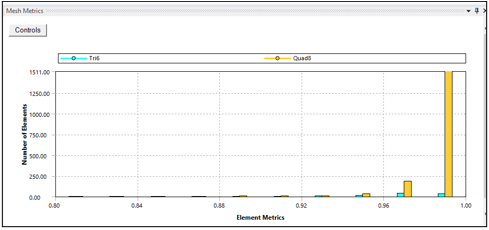
Figure 1.5: Mesh Element Quality Matrices
(Source: ANSYS)
In Figure 5, mesh element quality matrices range from 0.92 to 1, indicating excellent quality. These quality matrices show ANSYS analysis mesh element uniformity and appropriateness. Values near 1 indicate high-quality components, whereas 1 indicates full geometric congruence. This consistency guarantees the mesh correctly depicts geometry and minimizes simulation distortions. Such high-quality parts ensure the analysis's accuracy and dependability, improving the comprehension of the Rack and Pinion system's structural behavior.
4.3 Boundary Conditions
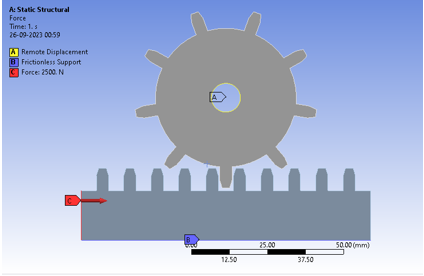
Figure 1.6: Boundary Conditions
(Source: ANSYS)
ANSYS boundary conditions are essential for modeling car rack and pinion steering systems. At point A, a Remote Displacement boundary condition allows the pinion to travel horizontally 30 mm in 1 second. This properly simulates steering wheel rotation, and starting rack action. Point B uses a Frictionless Support to secure the rack to the chassis by limiting all degrees of freedom. This keeps the rack immobile throughout the simulation, imitating its real-world use. These boundary conditions allow the study to derive performance characteristics like the reaction force at the pinion, which affects steering effort. Stress and deformation values of rack and pinion components are also assessed to determine system structural integrity.
4.4 Solver Settings
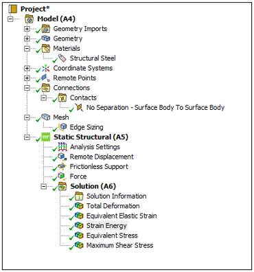
Figure 1.7: Solver Settings
(Source: ANSYS)
The above figure shows the solver setting for the analysis.
5. Results
The Rack and Pinion system's complete ANSYS study reveals its mechanical behavior under different situations. Under properly constructed boundary conditions, this approach explains the system's deformation, stress distribution, and contact mechanics. Similar to a vehicle's steering system, boundary conditions imitate real world events, making these discoveries important to engineering (Khalifa, 2023). These discoveries improve Rack and Pinion system design, efficiency, and safety, advancing mechanical engineering practices and assuring dependable performance in varied engineering settings.
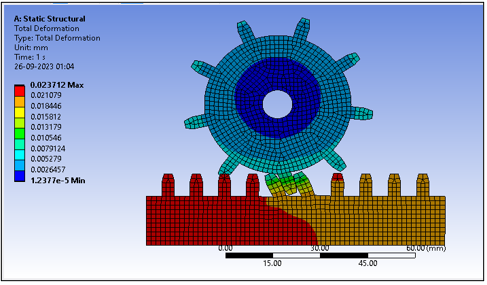
Figure 1.8: Total Deformation
(Source: ANSYS)
Total Deformation analysis, based on boundary conditions, provides valuable insights into Rack and Pinion system structural behavior. The system's minimal deformation value of 1.24E 05 indicates structural integrity under operating loads. Even while 2.37E 02 is high, it's within acceptable limits, showing the system's stress tolerance. The boundary conditions simulate real world circumstances well since the average deformation of 1.20E-02 shows a balanced reaction to applied forces. These findings confirm the system's stability and give crucial data for design and safety improvements.
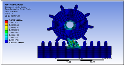
Figure 1.9: Elastic Strain Distribution
(Source: ANSYS)
Elastic Strain Distribution study inside the boundary conditions exposes Rack and Pinion system deformation properties. Under these circumstances, the minimum elastic strain is 4.5975e 010, indicating structural stability. The maximal score of 1.2389e 003, albeit higher, is within an acceptable range, suggesting moderate stress tolerance. At 5.7506e 005, the average elastic strain balances applied forces, proving that boundary conditions simulate real-world events. These insights aid system dependability and design optimization.
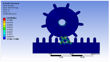
Figure 1.10: Strain Energy
(Source: ANSYS)
Strain Energy measured in mJ (millijoules) provides valuable insights into the Rack and Pinion system's mechanical behavior under defined circumstances. Little energy contribution of 5.54E-13 mJ suggests little system deformation or strain. However, the highest value of 0.8708 mJ, although larger, is within an acceptable range, reflecting the system's energy absorption and release. The system's energy distribution is balanced by the average Strain Energy of 29.585 mJ. These findings verify the system's structural integrity, aiding design and performance evaluation.
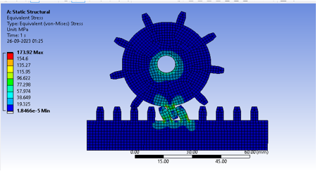
Figure 1.11: Equivalent Stress
(Source: ANSYS)
Equivalent Stress, measured in MPa (mega pascals), gives essential insights into the Rack and Pinion system's mechanical behavior under boundary circumstances. Minimum stress of 1.85E-05 MPa indicates exceptionally low stress levels, indicating a safe and stable system. While greater, the maximum stress measurement of 173.92 MPa is below critical failure criteria, proving the system can handle heavy loads. The average stress level, 10.677 MPa, shows that the boundary conditions simulate real-world events by responding evenly to applied forces. These findings are crucial for system design optimization and safety evaluations.
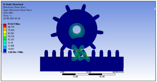
Figure 1.12: Maximum Shear Stress
(Source: ANSYS)
Maximum Shear Stress, measured in MPa (mega pascals), discloses important mechanical behavior of the Rack and Pinion system within the boundary conditions. Under these circumstances, the system's stability is shown by its minimum shear stress value of 1.0639e 005 MPa. At 97.621 MPa, the system's maximum shear stress is below critical limits, proving its durability. Due to the components' balanced shear stress of 5.8611 MPa, the boundary conditions accurately simulate real-world operating settings. These findings aid design and safety assessments.
6. Discussion
A thorough examination of the Rack and Pinion system using ANSYS software and boundary conditions revealed its mechanical behavior. These discoveries have major consequences for engineering design, performance optimization, and safety in different applications, especially rack and pinion steering systems in cars.
The system's deformation behavior is crucial to this investigation. System structural stability is shown by the minimal deformation of 1.24E 05. The system remains intact under boundary circumstances replicating the steering wheel's rotation, demonstrating its real world dependability. Though greater, the system's maximum deformation value of 2.37E 02 is within acceptable limits, demonstrating operational load capacity.
Evaluating the Elastic Strain Distribution strengthens the system. The minimal elastic strain of 4.5975e-010 shows that the system can withstand forces and preserve its form. The system can handle modest strain without deforming since the maximum value of 1.2389e-003 is tolerable.
Strain Energy analysis in millijoules emphasizes the system's energy intake and release. It shows modest deformation and strain with a minimum energy contribution of 5.54E-13 mJ. The highest value of 0.8708 mJ is substantially below critical limits, suggesting system robustness under load.
Equivalent and Maximum Shear Stress studies reveal the system's structural integrity. The minimal values of 1.85E 05 MPa and 1.0639e-005 MPa indicate that the system performs securely under difficult situations. Equivalent Stress is 173.92 MPa and Maximum Shear Stress is 97.621 MPa, significantly below failure criteria, demonstrating the system's capacity to bear heavy loads.
This research shows that the Rack and Pinion system is resilient and reliable under actual operating circumstances, as simulated by boundary conditions. These results influence design choices, allowing engineers to optimize system performance, safety, and effectiveness in varied engineering applications, notably automobile steering systems.
7. Conclusion
In conclusion, ANSYS Workbench software and carefully defined boundary conditions allowed for a thorough investigation of the Rack and Pinion system's mechanical behavior. These discoveries help improve the knowledge and performance of this basic mechanical arrangement utilized in many technical fields, including car steering systems.
Under boundary circumstances, the Rack and Pinion system shows low deformation, negligible elastic strain, and the capacity to absorb energy and carry the load. Maximum stress is substantially below critical limits, boosting system resilience.
These findings demonstrate the Rack and Pinion system's dependability and efficiency, making it suitable for demanding engineering applications. They also provide a solid platform for design refinement, optimization, and safety evaluations, advancing mechanical engineering practices and assuring Rack and Pinion system reliability in a variety of real world circumstances.
Workshop 4
1. Introduction
Structural analysis in engineering and materials science involves component interaction under mechanical limitations and pressure gradients. This study examines the difficult issue of shrink fit stresses between two cylindrical constructions using ANSYS Workbench software. This comprehensive research examines the complex relationship between geometrical limitations, internal pressure, and material characteristics of these cylinders, revealing important engineering design and structural integrity insights. The five components of this report's analysis are carefully selected to cover particular research aspects. The report starts with a thorough issue description and assumptions, laying the groundwork for later analysis. After discussing boundary conditions, loadings, solver settings, and meshing procedures in ANSYS Workbench, the computational framework is fully understood. ANSYS simulation data and analysis are the report's focus. It reveals the complicated stress distribution patterns in cylinders, providing critical insights into key areas, based on good theoretical concepts and thick cylinder theory. Post processing describes the methods and software used to extract and analyze crucial stress data. Therefore, this study synthesizes the investigation's findings and compares ANSYS results to theoretical predictions. The debate emphasizes the report's importance, making suggestions and highlighting its applicability to engineering applications. This thorough examination provides detailed knowledge of shrink-fit stresses between cylindrical structures, strengthening structural design approaches and setting the framework for additional research on this crucial topic.
2. Problem Description
Shrink fit between two cylinders is a major issue in mechanical engineering and structural analysis (Lee, and Hong, 2022). This study uses ANSYS Workbench software to analyze this phenomenon using finite element analysis (FEA). The issue involves two hollow cylinders with similar lengths, 'l,' concentrically positioned such that the inner cylinder is shrink-fitted into the outer one. In engineering, shrink fittings are used to link cylindrical components like shafts and bearings to transfer torque and axial loads.
This model's boundary conditions are crucial: both cylinders are restrained from axial movement, like a shrink fit, while preserving radial and tangential degrees of freedom. Inner cylinder pressure, 'P,' is applied. This analysis seeks to understand the stress distribution within these cylinders under internal pressure and identify the maximum tangential stresses, which are crucial to assessing assembly structural integrity (Feng et al. 2022). These results affect mechanical component design and performance evaluation and are essential for engineering system dependability and safety.
3. Assumptions for analysis
- A uniform temperature: This study ignores temperature changes and thermal impacts. The study assumes a constant assembly temperature.
- Geometry: The analysis assumes axisymmetric geometry, enabling a 2D axisymmetric model to reduce computer cost while retaining radial accuracy.
- The study assumes steady-state conditions, ignoring transient impacts like temperature variations or assembly.
- Assuming a perfect interference fit, this study does not account for material deformation or removal during shrink fitting (Ozbolt et al. 2022).
- Linear Pressure Distribution: The inner cylinder's inner surface has a linear pressure distribution depending on the internal pressure, P.
- Materials are expected to be constant and uniform across each cylinder's capacity.
- To simplify, the system is not loaded with external loads like axial or lateral loads.
4. Analysis Methods
A systematic approach was taken to analyze shrink fit stresses between two cylindrical structures using ANSYS Workbench, including model design, material assignment, mesh generation, boundary conditions, and result parameter definition (Wang et al. 2022). Methods used in the analysis are given here.
4.1. Modelling
First, ANSYS Workbench was used to create a 3D model of the two cylindrical components. Both cylinders' inner and outer radii and length (l), 100 mm, were exactly determined. The model appropriately depicts the shrink-fit assembly's geometry.
.png)
Figure 4.1: Geometry
(Source: ANSYS)
Figure 4.1 shows the ANSYS created shrink fit assembly geometry. The model's two cylindrical parts are precisely crafted to mimic engineering circumstances. The inner cylinder, with a 30 mm inner radius and 40 mm outside radius, is precisely crafted to imitate the assembly's fundamental component. Its proportions are carefully designed to mirror the innermost piece of the shrink fit arrangement, emphasizing its crucial role in assembly structural integrity. With an inner radius of 39 mm and an outside radius of 50 mm, the outer cylinder encloses the inner cylinder. This geometric shape perfectly mimics the shrink-fit assembly's outer component, emphasizing these two cylinders' interaction.
4.2. Material Assignment
Components were given material attributes to imitate cylinder mechanical behavior. The material was consistent for both cylinders. The material's elastic response to external forces was determined using Young's modulus (E) and Poisson's ratio (v).
.png)
Figure 4.2: Material Assignment
(Source: ANSYS)
Figure 4.2 shows the FEA model's material assignment. Steel, known for its strength and longevity, was chosen for the inner cylinder. Aluminum, which is lightweight and thermally conductive, was used for the outside cylinder. This planned material choice was designed to emulate a genuine engineering situation where various materials are routinely utilized in cylindrical assemblies, enabling stress interactions under internal pressure to be evaluated. Material assignments are crucial to accurately representing and analyzing the model's mechanical behavior.
4.3. Mesh creating
Meshing is crucial to FEM. A mesh was created for model correctness. For precise stress gradients, finer meshing was used in locations of importance like the cylinder contact interface (Cheng et al. 2022). Optimal element types and sizes were chosen to balance computing efficiency and accuracy.
.png)
Figure 4.3: Mesh
(Source: ANSYS)
The FEA model was rigorously meshed with 1 mm elements. This produced a polished mesh with many nodes and components. The mesh correctly represented complicated geometry and enabled exact stress and displacement calculations using 662,332 nodes and 146,046 components. To capture stress gradients, particularly in locations of importance like the contact interface between the two cylinders, the fine element size and extensive meshing were used. FEA findings are more accurate and robust with this small mesh resolution.
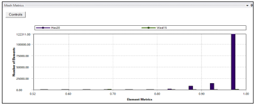
Figure 4.4: Mesh Element Matric Quality
(Source: ANSYS)
Figure shows the element quality distribution in the analyzed model's finite element mesh. The findings show element quality levels from 0.9 to 1.0. Element quality measures the mesh's geometric and structural integrity. A score of 1.0 indicates optimal, high quality parts, whereas values below 1.0 indicate deviations. The graphic shows the mesh's resilience and where element quality may differ from ideal. Finite element analysis requires excellent element quality, and this representation optimizes the mesh for accurate findings.
4.4. Boundary Conditions:
Creating shrink fit limitations and loadings, boundary conditions were created. The smooth surfaces of both cylinders were limited axially to simulate shrink fit assembly axial movement resistance. With radial and tangential degrees of freedom, the model simulated unconstrained movement in these directions.
.png)
Figure 4.5: Boundary Conditions
(Source: ANSYS)
In this ANSYS Workbench FEA, 500 MPa was supplied to the inner cylinder's inner surface to simulate internal pressure. This boundary condition simulates hydraulic or pneumatic stresses on cylindrical components. Fixed supports were placed on the flat surfaces of both cylinders to simulate shrink fit assembly limitations and prevent axial movement. The FEA model's structural analysis is based on these boundary conditions, which properly describe cylindrical constructions' key mechanical restrictions and loadings.
4.5 Solver Setting
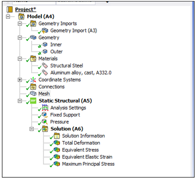
Figure 4.6: Solver setting
(Source: ANSYS)
The attached figure shows the applied solver setting for the analysis where it can be noticed that different tools and functions have been applied here to gen the analysis.
5. Results
In the findings section, the finite element analysis (FEA) results are thoroughly examined to understand shrink fit assembly behavior. Deformation, stress distributions, and critical tangential stresses are covered in this section. The cylindrical system's structural integrity and performance are illuminated by detailed examination of deformation patterns, stress concentration locations, and tangential stresses. These ANSYS Workbench findings provide a comprehensive view of the complicated interaction between geometry, material characteristics, and applied loads, helping engineers comprehend cylindrical assemblies
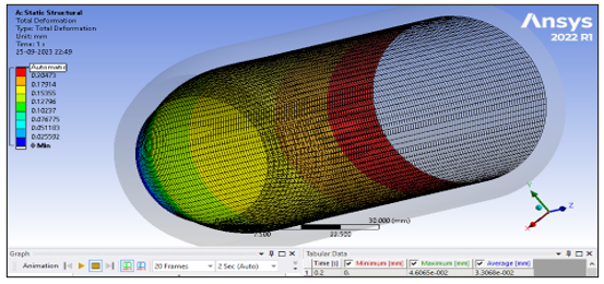
Figure 4.7: Total Deformation
(Source: ANSYS)
Total shrink fit assembly deformation is shown in the figure. The model had a maximum distortion of 0.23032 mm and an average of 0.16534 mm. These deformation values indicate the cylindrical components' movement under internal pressure. Deformation patterns are essential for measuring the assembly's mechanical reaction and design tolerances, as seen in the picture. This study helps ensure the structural integrity and functioning of such assemblages in engineering applications.
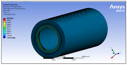
Figure 4.8: Tangential stress as maximum principle stress
(Source: ANSYS)
The tangential stress distribution in the shrink-fit assembly is shown in the figure. The greatest principle stress was 4583 MPa, with an average of 562.35 MPa. Tangential stress was lowest at 745.55 MPa. These data show complicated and varied assembly stress conditions. These insights help evaluate structural integrity and material failure by detecting crucial stress concentrations. This stress study provides a complete insight of the assembly's performance and significance to engineering design and safety.
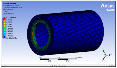
Figure 4.9: Elastic Strain
(Source: ANSYS)
The shrink-fit assembly's elastic strain is shown in the image. It shows elastic strain values from 6.6497e 020 to 1.7762e-002. The average elastic strain throughout the model was 3.0927e-003. These strain metrics reveal regions of minor and large elastic strain in the assemblage, revealing its deformation behavior. Understanding elastic strain distribution is crucial for understanding structural response and possible assembly deformations under load. This study optimizes the cylindrical system's design and ensures safety and performance.
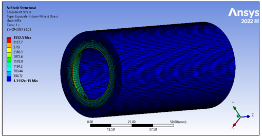
Figure 4.10: Equivalent Stress
(Source: ANSYS)
The graphic shows the shrink-fit assembly's comparable stress distribution. The model shows comparable stress values from 617.92 MPa to 3552.5 MPa. This approach simplifies assembly stress into a single variable, improving structural performance measurement. The graphic shows areas of high stress, directing engineering choices to ensure assembly integrity and safety. These conclusions, derived via careful study, optimize design parameters and reduce failure risks in real engineering applications.
6. Discussion
ANSYS Workbench study of the shrink fit assembly revealed its structural behavior and mechanical response. This discussion summarizes the study's main results and ramifications, emphasizing the cylindrical coordinate system's tangential stresses in ANSYS Workbench.
Tangential stress calculations were crucial to this approach. The research examined assembly tangential stresses using ANSYS Workbench's cylindrical coordinate system. This method allows for a thorough analysis of stress fluctuations throughout cylindrical components, identifying crucial stress concentrations. The data show maximum tangential stresses of 4583 MPa and an average of 562.35 MPa. Positive and negative stress values show the assembly's complicated stress distribution, revealing structural flaws.
The research also explained elastic strain and deformation patterns. Component displacement under internal pressure is shown by a maximum deformation of 0.23032 mm. Elastic strain readings from 6.6497e-020 to 1.7762e 002 mm showed the assembly's complex elastic response. These results elucidate deformation behavior, enabling structural compatibility and real-world loading deformation evaluation.
The finite element mesh element quality distribution was also carefully investigated. We found element quality scores from 0.9 to 1.0, with higher values indicating better organization. For proper analysis, element quality must be excellent, and the figure optimized the mesh for exact findings. Therefore, the ANSYS Workbench study of the shrink fit assembly revealed its mechanical reaction in several ways. Tangential stresses, deformation patterns, and element quality improve structural design and reliability, guiding engineering decisions and emphasizing the importance of using the cylindrical coordinate system in ANSYS for such complex analyses. Practical engineering applications benefit from these insights for cylindrical assembly integrity and safety.
7. Conclusion
In conclusion, ANSYS Workbench's complete shrink fit assembly analysis revealed its mechanical behavior and structural reaction. The study's multimodal approach tangential stresses, deformation patterns, and element quality assessments provided crucial insights for engineering design and safety. Complex stress distributions were found in tangential stress analysis using ANSYS Workbench's cylindrical coordinate system. These results help reveal structural weaknesses and guide optimization. For design tolerance compatibility, deformation patterns, and elastic strain showed displacement and the assembly's elastic response under loads. In addition, element quality assessment showed the mesh's resilience, assuring accurate finite element analysis findings. This investigation shows the need to use sophisticated simulation methods to evaluate cylindrical assembly structural integrity and performance. These findings guide engineering choices, improving design processes and ensuring real-world safety.
Workshop 5
ANSYS Workbench was used to do a finite element analysis (FEA) on the shrink fit between two cylinders. The following assumptions were applied to simplify the actual case and approximate the system's behavior:
- Under stress, both cylinders' materials are considered to be linear elastic. Classical stress analysis is possible with this assumption.
- Isotropic Materials: The cylinders' mechanical characteristics, such as Young's modulus and Poisson's ratio, are uniform (Loc, and Phong, 2022).
- Perfect Contact: The outer surface of the inner cylinder and the inner surface of the outer cylinder have no gaps, discontinuities, or interfacial friction.
1. Introduction
The study on the solid bracket model is a complete examination of ANSYS Mechanical's Fatigue Module fatigue evaluation. A solid bracket is exposed to cyclic stress to assess its structural integrity and fatigue life. This study uses the strain-life technique, a well established method for estimating the fatigue performance of materials and components when repeatedly loaded. This sturdy bracket has limitations at one end and a 1000 N load at the other. Fatigue calculations use a notional load of 3000 N to account for operational loading variances. This examination determines if the bracket can withstand these cyclic stress conditions for 1e5 cycles (100,000 cycles) without fatigue-induced failure. The fatigue analysis approach will be explained. Important procedures include material characterization, finite element mesh development, boundary condition application, and fatigue analysis parameter setting. Present and analyze simulation data to assess whether the bracket satisfies design life requirements. This study's results are crucial for design choices and bracket structural reliability and safety margins. This study helps engineers and researchers evaluate structural component fatigue performance using modern finite element analysis tools like ANSYS Mechanical.
2. Problem Description
The issue at hand is determining the structural integrity and performance of a solid bracket under cyclic loads via a thorough fatigue investigation. The strain life technique is used in this ANSYS Mechanical study to reliably forecast the service life of a component subject to fatigue.
A cyclic loading regime is applied to the solid bracket in question, with a nominal load of 3000 N being taken into account and a starting load of 1000 N being applied. The main goal is to determine whether this bracket can withstand these cyclic stress circumstances for the specified design life of 1e5 cycles (equal to 100,000 cycles) without failing due to fatigue. In engineering design, where parts are subjected to repeated loads during their service lives, these analyses are crucial. It is assumed, first and foremost, that the simulation faithfully represents the stress-strain behavior and fatigue characteristics of the bracket's material. If you want your analysis to accurately represent how the bracket is loaded, you need to provide accurate boundary conditions that mimic the real world working environment (Ramkumar et al. 2021). Essential for making educated engineering choices and maximizing component dependability and safety, this issue description serves as the basis for a thorough fatigue analysis of the solid bracket using ANSYS Mechanical.
3. Assumptions
Several simplifications and assumptions must be made to make the computational simulation and analysis of fatigue possible in ANSYS. Although these assumptions are required for practical analysis, they should be well-defined so that the findings may be properly comprehended.
- The bracket material is considered to be homogenous and isotropic, meaning that its mechanical characteristics are uniform over the whole construction and independent of orientation.
- Within the elastic limit, stress is proportional to strain, hence the behavior of the material is believed to be linear elastic. The modeling of material behavior is simplified with this assumption (Althaf et al. 2021).
- The study is conducted on the assumption of a constant temperature during the whole loading cycle. The effects of temperature changes on a material's characteristics should be taken into account if they are relevant.
- Large deformations and other important geometric nonlinearities are disregarded, hence there is no nonlinear geometry. As long as the stresses involved are relatively minor, this simplification is true (Damre, and Jadhav, 2020).
- The study is performed on the hypothesis that plastic deformation does not occur in the material throughout the loading cycles. The influence of plasticity, which may greatly modify fatigue behavior, is neglected here.
- The applied load is thought to be static and evenly distributed. We ignore the possibility of dynamic effects or fluctuations in loading.
- In the fatigue analysis, it is assumed that the cyclic loading conditions would remain relatively consistent during the design life.
This study does not take into account any residual stresses that may exist as a result of the manufacturing process or previous loading circumstances.
Predictions of fatigue life are the primary focus of the linear elastic fracture mechanics (LEFM) study. It is predicated on the idea that cracks start and spread due to cyclic stress alone.
The study is simplified and made computationally possible by making certain assumptions. The real-world behavior of the bracket and its operating circumstances should be compared to the theoretical ones. More complex modeling approaches and considerations may be needed if these assumptions are violated in real-world circumstances.
4. Methodology
4.1 Geometry and material assignment
Performing the analysis there has been considered a solid bracket model and various functions and techniques are applied here to analyze the fatigue and other parameters as described below.
.png)
Figure 5.1: Solid Bracket Geometry
(Source: ANSYS)
A solid bracket is seen in its geometric structure in Figure 1. The bracket has a strong rectangular form, with one end being restrained and the other being loaded. For structural analysis and fatigue evaluation using ANSYS Mechanical, its dimensions and attributes are critical.
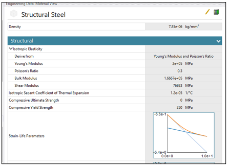
Figure 5.2: Structural Steel material assigned
(Source: ANSYS)
As shown in Figure 2, the material for this part is Structural Steel. Because of its excellent strength and endurance, this material is well-suited for use in structural contexts. The stress-strain relationship and fatigue characteristics are used in the study to determine how well the bracket performs under cyclic loading.
4.2 Mesh Generation
In order to do finite element analysis, the ANSYS software performs a process called "mesh generation," which involves breaking down a complicated geometric model into a network of tiny, linked elements (usually triangles or quadrilaterals for 2D and tetrahedral or hexahedra for 3D). ANSYS can then compute stress, strain, and other engineering characteristics at discrete places inside each element thanks to the mesh's subdivision of the model into digestible chunks (Sener, 2021). The precision and speed of computational simulations depend critically on good meshing. To guarantee an accurate depiction of the geometry and physical behavior during simulations, engineers establish mesh parameters such as element size and type.
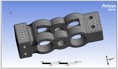
Figure 5.3: Mesh Generation
(Source: ANSYS)
A finite element mesh with a 2 mm element size is shown in Figure 3. A total of 126,240 nodes and 85,609 elements make up the mesh, each of which represents a separate feature of the solid bracket geometry. Stress, strain, and deformation can all be accurately calculated over the whole bracket under the imposed loading conditions because of the mesh generation used in the structural analysis performed in ANSYS.
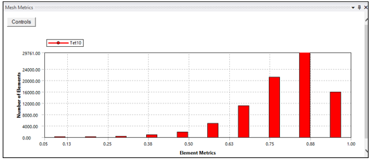
Figure 5.4: Mesh Element Quality
(Source: ANSYS)
Figure 4 presents a histogram of Mesh Element Quality values between 0.63 and 1 for ease of interpretation. These numbers indicate the standard of the mesh's finite elements. Elements with a value of 1 have no geometric abnormalities or distortions, whereas those with a value closer to 0.63 have. For reliable finite element analysis, the majority of the mesh elements must be of reasonable quality, which is shown by a histogram in this range. The findings of the structural examination of the bracket are more solid when higher-quality elements are used.
4.3 Boundary Conditions
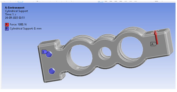
Figure 5.5: Boundary Conditions
(Source: ANSYS)
This approach relies on bracket boundary conditions to simulate real-world operating situations and properly evaluate structural integrity under cyclic loads. When the bracket is attached to a cylindrical support at position "B," all three degrees of freedom translational and rotational are entirely restricted. At this support point, the bracket cannot move or rotate. To keep the bracket in place, X, Y, and Z translational motion is limited to 0 mm. Restricting rotational movement around the X, Y, and Z axes to 0 degrees prevents rotation. At "A," a 1000 N cyclic load is applied in the image direction. In operation, the bracket will experience this load. A cyclic load is applied to recreate the bracket's recurrent loading conditions over time.
4.4 Solver Settings
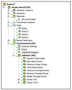
Figure 5.6: Solver Settings
(Source: ANSYS)
The attached figure shows the applied solver setting for the fatigue analysis on the solid bracket model.
5. Results
In this section, there has been discussed the obtained results from the fatigue analysis.
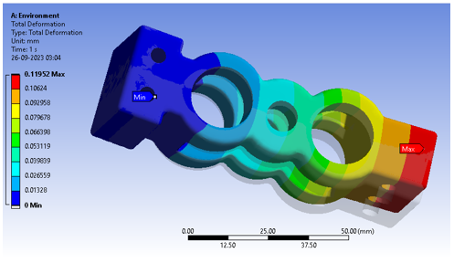
Figure 5.7: Total Deformation
(Source: ANSYS)
Total Deformation analysis findings for the bracket are shown in Figure 5.7. The research shows significant deformation features under cyclic stress. The bracket stays constant or deforms little in locations with 0.00E+00 mm displacement. The maximum deformation measurement of 1.20E-01 mm indicates bracket locations with the largest distortion, presumably where the cyclic load is strongest. The bracket's structure deforms on average 3.63E-02 mm. These findings help evaluate the bracket's structural integrity and fatigue-related issues under real-world operating settings by analyzing its reaction to cyclic loads.
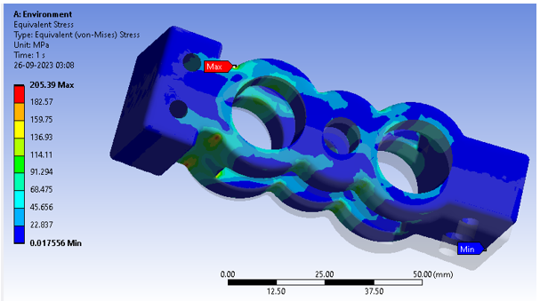
Figure 5.8: Equivalent Stress
(Source: ANSYS)
Equivalent Stress analysis in Figure 5.8 reveals bracket structural performance. The bracket exhibits the lowest stress at 1.76E-02 MPa, possibly where the imposed cyclic load has little effect. However, the maximum stress measurement of 205.39 MPa reveals bracket sections with the greatest stress, usually near load application. The bracket's stress distribution is represented by the average stress of 22.326 MPa. These data are essential for analyzing the bracket's cyclic loading resistance and structural integrity within operating limitations.
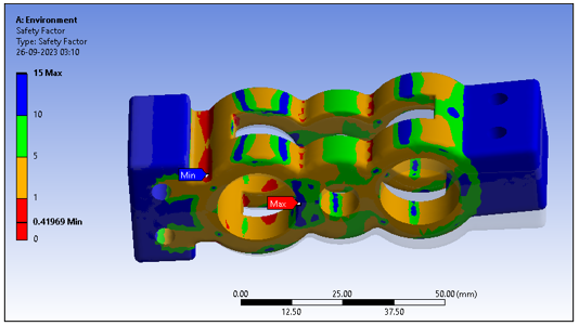
Figure 5.9: Safety Factor
(Source: ANSYS)
In Figure 5.9, the Safety Factor analysis findings are used to assess the bracket's structural integrity and dependability under cyclic loads. A minimal safety factor of 0.41969 indicates bracket locations where load-carrying capability is near to applied load. The bracket areas with the maximum safety factor value of 15 have a large safety margin, with load-carrying capabilities beyond the imposed load. The bracket's construction quality is assessed by its average safety factor of 7.9592. High values indicate structural robustness and safety, which is crucial for bracket safety and performance.
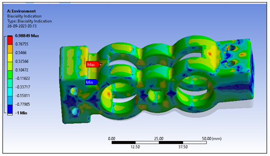
Figure 5.9: Biaxiality Indication
(Source: ANSYS)
The Biaxiality Indication findings in Figure 5.9 reveal the bracket's biaxial stress. The minimal value of -1 shows locations with high biaxial tension, possibly prone to stress concentration. The maximum score of 0.98849 indicates areas with mostly uniaxial stress and lesser Biaxiality, indicating they may be less prone to stress concentration. The bracket's biaxial stress distribution is shown by the average Biaxiality of -0.16852. These data help detect stress concentrations and evaluate the bracket's structural performance under complicated loading situations.
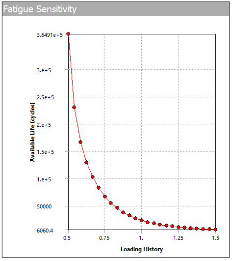
Figure 5.10: fatigue Sensitivity
(Source: ANSYS)
The plots show fatigue sensitivity in a solid bracket under different loading histories and boundary circumstances. Note that fatigue sensitivity rises with loading cycles for the bracket. This implies that the bracket becomes increasingly prone to fatigue-induced failure with time, emphasizing the need for long-term durability. The boundary circumstances affect fatigue sensitivity. Fatigue sensitivity is reduced in the bracket with a fixed support at position "B". The support's capacity to reduce bracket stress concentrations increases fatigue resistance.
6. Discussion
The complete fatigue investigation of the solid bracket in this paper has shown its structural performance and durability under cyclic stress. Analysis shows the bracket's fatigue sensitivity is crucial. More loading cycles enhance the bracket's fatigue failure risk. Boundary circumstances strongly affect fatigue sensitivity. The bracket with stable support at point "B" has decreased fatigue sensitivity, demonstrating how good support structures reduce stress concentrations. The safety factor study shows that the bracket's load-carrying capability easily surpasses the applied load in most places. This study has evident design implications. Engineers must examine material qualities, boundary conditions, and stress concentration variables to improve fatigue resistance. These parameters may be tuned to make the bracket fatigue-resistant under prolonged cycle loads. This research is important for engineers and designers dealing with comparable structural components. They help improve fatigue resistance, boosting component dependability and safety in real-world applications.
7. Conclusion
In conclusion, the fatigue study of the solid bracket has shown its structural performance under cyclic stress. The results emphasize the relevance of fatigue sensitivity in engineering design, especially for repetitively loaded components. This reduction in fatigue sensitivity as the bracket loads more emphasizes the need for fatigue evaluation. This research shows that boundary conditions affect the bracket's reaction to cyclic stress, with stable support at point "B" minimizing fatigue susceptibility. A high safety factor across the bracket demonstrates its strong static strength under specified loading circumstances. It also advises further optimization to improve fatigue resistance. To maximize structural component fatigue life, engineering practice must take a holistic approach that encompasses material qualities, boundary conditions, and design methodologies. The results of this research may help engineers and designers verify the dependability and durability of identical components in real-world applications.
References
.png)
.png)
MME501 Materials of Engineers Report 3 Sample
Task 1:
Case Study on Materials Used in Modern Aircraft:
Carefully read the below text and answer the following questions.
It is strongly suggested to refer to the lecture notes, recommended textbooks, and other literature in formulating your answers. It is not necessary to use question numbers, but make sure to provide sufficient explanations to cover the questions.
You may use figures, diagrams and tables to illustrate your answer and provide citations and references, where necessary.
The answer should contain a minimum of 500 words.
“Composite materials have been called the shape of aerospace’s future. With their winning combination of high strength, low weight and durability, it’s easy to see why. For more than 30 years, Airbus has pioneered the use of such materials in its commercial jetliners, from the cornerstone A310’s vertical stabiliser to today’s A350 XWB – on which more than half of the aircraft’s structure is composite.
In essence, a composite material is made from two or more constituent materials with different physical or chemical properties. When combined, the composite material exhibits beneficial physical characteristics quite different from what the individual components alone can provide. Commonly- recognised composites in everyday life include plywood and reinforced concrete.
From nose to tail, Airbus utilizes advanced composites in its jetliner product line that have been at the forefront of materials science. One particular standout material is carbon-fibre reinforced plastic, or CFRP. Composed of carbon fibres locked into place with a plastic resin, CFRP offers a better strength-to-weight ratio than metals and has less sensitivity to fatigue and corrosion. In short, it’s lighter than aluminium, stronger than iron, and more corrosion-resistant than both.
Like all composites, the strength of CFRP results from the interplay between its component materials. By themselves, neither the carbon fibres nor the resin is sufficient to create a product with the desired characteristics to be integrated on an aircraft. But once combined in multiple, integrated layers and bonded, the CFRP airframe component or aerostructure takes on the strength and load- bearing properties that make it ideal for aviation use.”
(Source: https://www.airbus.com)
Discuss advantages of using non-metals in aircraft structures.
Investigate the extent of usage of non-metals in A350 aircraft or a similar aircraft.
Compare the use of CFRP in A350 aircraft with traditional materials used for older versions of aircraft. It is required to compare strength, durability and other key properties and quote suitable examples of components for which these different materials are used.
Investigate the limitations of using non-metals in aircraft structures.
Task 2:
“Strain hardening is the phenomenon whereby a ductile metal becomes harder and stronger as it is plastically deformed. Sometimes it is also called work hardening, or, because the temperature at which deformation takes place is “cold” relative to the absolute melting temperature of the metal, cold working. Most metals strain harden at room temperature” – Materials Science and Engineering, Callister, 8th Edition
The figure on the left below demonstrates how steel, brass, and copper increase tensile strength with increasing the degree of cold work. The price for this enhancement of strength is in the ductility of the metal. The reduction in ductility with the percentage of cold work is shown in the figure on the right.
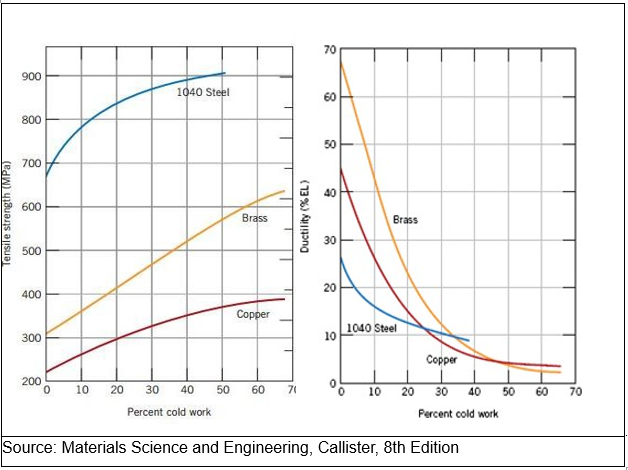
Source: Materials Science and Engineering, Callister, 8th Edition
Once a cold worked material is heat treated, the recrystallization process resets the cold work properties to zero cold work case. Therefore, when excessive cold work is required without sacrificing the ductility of a material, a component is partially cold worked which is followed by heat treatment to reset the properties before the next stage of cold work. This process may be repeated for number of times as required.
Use the above explanation and the graphs to answer the following questions.
A cylindrical rod of brass originally 10.2 mm in diameter is to be cold worked by drawing. The circular cross section will be maintained during deformation. A cold-worked tensile strength in excess of 380 MPa and a ductility of at least 15 %EL are desired. Furthermore, the final diameter must be 7.6 mm.
Hint: The following process may be followed to achieve the requirement.
Calculate the percentage cold work expected during the drawing which reduces the diameter from 10.2 mm to 7.6 mm. Use the given diagrams to justify that the required tensile strength and/or the ductility cannot be matched with the proposed amount of cold work.
As an alternative, consider the required values of tensile strength and the ductility, separately to determine the target values of percentage of cold work and hence propose a suitable range for the percentage of cold work. Considering the range, decide on a suitable amount of cold work.
It is suggested that to reduce the diameter of the rod to an intermediate value to satisfy the proposed percentage of cold work in b) above. Apply the cold work formula to determine the final diameter of the rod after this first stage of the cold work.
Explain the rest of the process of reducing the cross section to 7.6 mm diameter whilst achieving the required ductility and tensile strength. What is the percentage of cold work retained in the rod?
Task 3: (30 marks)
3.1
It is required to select suitable material/s for an engineering application that satisfies the following requirements:
Tensile strength more than 700 MPa
Modulus of elasticity more than 100 GPa
Density less than 3000 kg/m3
3.2
Answer following questions.
Use the first two Ashby charts (below) to select a set of materials that satisfy these requirements.
Use the third Ashby chart, standard textbooks and/or any other resource/s to refine your selection to present three best materials if the following additional requirements are also to be fulfilled.
Corrosion resistance
Low cost
Sustainability
Explain the selection process in each case quoting any references used.
.png)
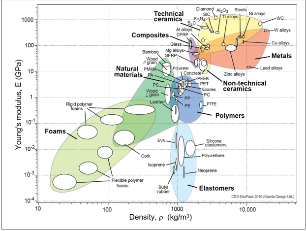
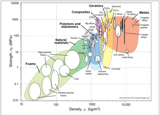
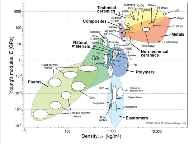
Solution
Task 1 (a)
In contrast to conventional metals, the use of non-metallic materials, particularly composites, offers a number of benefits. Here are a few of the main advantages:
1. Excellent strength to weight ratio: Composites outperform conventional metals in this regard. For instance, aluminium is substantially heavier than carbon fibre reinforced plastic (CFRP), a prominent composite material used in aerospace applications, but it has comparable or even higher strength.
2. Durability: In difficult situations, composites are also more durable than conventional metals. They are perfect for aviation constructions that must withstand harsh circumstances since they are less sensitive to fatigue and corrosion.
3. Design Adaptability: Composites may be shaped into intricate forms, increasing design adaptability and maximising material usage. Reduced weight and improved fuel economy are the outcomes, which are crucial for commercial aircraft.
4. Lower Maintenance Costs: Due to their longevity, composites need less maintenance than conventional metals. Over the course of an aircraft, this can save a lot of money.
5. Better Performance: Using composite materials in aircraft constructions can lead to better performance, especially in terms of speed, range, and cargo capacity. This is due to the fact that composites have a greater strength-to-weight ratio, which leads to improved efficiency and performance.
Task 1 (b)
Modern commercial aircraft like the Airbus A350 XWB (Extra Wide Body) heavily rely on non-metallic components, notably composites. In reality, composite materials, including carbon-fibre reinforced plastic (CFRP) and other cutting-edge materials, make up more than half of the aircraft's construction. Here are some instances of how the A350 uses composite materials:
1. The A350's wings are predominantly constructed of CFRP, which is stronger and lighter than aluminium. By stacking pre-impregnated carbon fibre material in a mould and then curing it at high temperatures to form a solid, one-piece structure, a novel manufacturing technique is used to manufacture the wings.
2. Fuselage: Materials like as CFRP and other composites are used to construct the A350's fuselage. Similar stacking and curing techniques are used to create the fuselage to generate a sturdy, light-weight structure that is corrosion- and fatigue-resistant.
3. The A350's horizontal tail plane and vertical stabiliser are likewise composed of composite materials, including CFRP. To build a sturdy, lightweight framework, these components are made utilising a combination of manual lay-up and automated lay-up procedures.
4. Landing Gear Doors: GLARE (Glass Laminate Aluminium Reinforced Epoxy), a composite material, is used to construct the landing gear doors of the A350. The hybrid material GLARE is made of layers of fibreglass and aluminium, creating a robust, light-weight framework that is resistant to fatigue and corrosion.
Task 1 (c)
The A350 aircraft's usage of CFRP marks a substantial change from the conventional materials used in earlier models of aircraft. Some of the main variations between the two are as follows:
Strength: Compared to conventional materials like aluminium or steel, CFRP offers a better strength-to-weight ratio. For instance, the wing of the A350 XWB is entirely composed of CFRP, which results in a weight savings of 25% when compared to a traditional metal wing of comparable size. Lower running costs and improved fuel economy are the consequences.
Durability: Compared to conventional metals, CFRP is less prone to corrosion and fatigue. For instance, the 53% CFRP fuselage of the A350 XWB makes it more corrosive resistant and less prone to fatigue fractures. Longer service life and lower maintenance expenses result from this.
Component examples: In addition to the wing and fuselage, the A350 XWB also heavily utilises CFRP in the tail section, nose cone, and doors.
Task 1 (d)
There are several advantages for The Assignment help to using non-metals, notably composites, in aeroplane construction, as the text emphasises. There are several restrictions to take into account, though:
1. Price: Producing composite materials may be expensive and necessitates specialised production techniques. The materials themselves may be more expensive than conventional metals, and the initial investment in production-related tools and training may be high.
2. Maintenance: Compared to typical metal constructions, composite structures may require more effort and time to fix. It may be necessary to purchase specialised tools and training, which will raise the overall cost of maintenance.
3. Robustness: Despite being more resilient than metals in general, composites might be more vulnerable to damage from external elements including UV light, dampness, and severe temperatures.
4. Fire resistance: Composite materials can be less fire-resistant than metals, and may require additional fireproofing measures to meet safety regulations.
Top of Form
Task 2 (a)
To calculate the percentage cold work, we can use the formula:
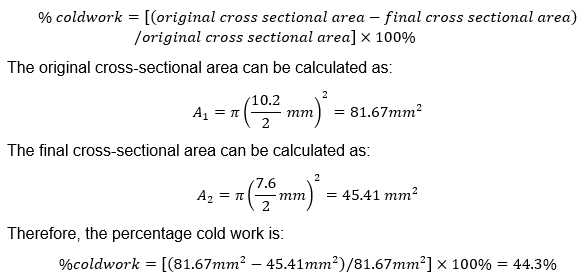
According to the figure on the left, brass's tensile strength improves as the amount of cold work increases; a cold-worked tensile strength of more than 380 MPa may be attained with a cold work of around 50%. The figure to the right shows, however, that brass's ductility rapidly declines as the amount of cold work increases, and a ductility of at least 15%EL cannot be obtained with a cold work of 50%. Because of this, the suggested level of cold work (44.3%) is insufficient to provide the appropriate levels of tensile strength and ductility.
Task 2 (b)
Looking at the figure on the left, we can see that a cold work of roughly 50% is necessary for brass in order to attain the appropriate tensile strength of 380 MPa. But as we can see from the figure on the right, a 50% cold work yields a ductility of less than 10%EL. Looking at the figure to the right, we can see that a cold work of less than 30% is necessary for brass in order to reach the needed ductility of at least 15%EL. But as we can see from the figure on the left, a 30% cold work yields a tensile strength of about 280 MPa, which is significantly less than the desired 380 MPa.
To attain the appropriate tensile strength and ductility, we must thus choose an acceptable range of cold work. The data show that a tensile strength of around 400 MPa and a ductility of about 12%EL may be obtained from a cold work of about 40%. In light of this, 35–45% of cold labour would be appropriate in this situation. We may select a 40% cold work, which is towards the middle of the range and should produce tensile strength of about 400 MPa and ductility of about 12%EL.
Top of Form
Task 2 (c)
To achieve a cold work of 40%, it is suggested to perform the cold work in multiple stages. Let's assume that the initial diameter of the rod is reduced to an intermediate value (D_i) such that the final diameter after the second stage of cold work is 7.6 mm.
From the formula for percentage cold work, we can write:
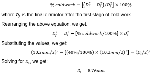
Therefore, the diameter of the rod should be reduced to 8.76 mm in the first stage of cold work, and then further reduced to 7.6 mm in the second stage of cold work to achieve a total cold work of 40%.
Task 2 (d)
To achieve a final diameter of 7.6 mm with a total cold work of 40%, the rod needs to be cold worked in two stages:
First stage: Reduce the diameter from 10.2 mm to 8.76 mm. This corresponds to a cold work of 14.1%.
Second stage: Reduce the diameter from 8.76 mm to 7.6 mm. This corresponds to a cold work of 26.1%.
After the first stage of cold work, the material should be heat treated to reset the cold work properties before the second stage of cold work. This is important to avoid excessive hardening and embrittlement of the material.
Assuming that the heat treatment successfully reset the cold work properties after the first stage, the total percentage of cold work in the final product will be:
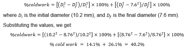
Therefore, the percentage of cold work retained in the rod after the second stage of cold work is 40.2%. Since this value is close to the target range of 35-45% calculated in part (b), we can expect the final product to have a tensile strength of about 400 MPa and a ductility of about 12%EL, as discussed earlier.
Task 3
It is required to select suitable material/s for an engineering application that satisfies the following requirements:
Tensile strength more than 700 MPa
Modulus of elasticity more than 100 GPa
Density less than 3000 kg/m3
Task 3 (a)
To satisfy the given requirements, we need to find materials with a high tensile strength and modulus of elasticity, while also having a low density. We can start by looking at materials with high tensile strength and modulus of elasticity from the first Ashby chart.
Materials such as titanium alloys, high-strength steels, and some aluminum alloys have high tensile strength and modulus of elasticity. However, these materials are generally dense and may not meet the density requirement.
To meet the density requirement, we need to look at materials with a low density from the second Ashby chart, such as carbon fiber composites or polymer-based materials. However, these materials typically have a lower tensile strength and modulus of elasticity compared to metals.
Therefore, we need to strike a balance between these requirements by selecting a material that offers a good compromise between strength, stiffness, and density. One such material that meets these requirements is carbon fiber reinforced polymer (CFRP). CFRP has a tensile strength of around 700-1400 MPa, a modulus of elasticity of 100-300 GPa, and a density of around 1600-1900 kg/m^3. Other composite materials such as fiberglass or Kevlar may also be suitable depending on the specific requirements of the engineering application.
Task 3 (b)
To refine our selection of materials, we will consider the additional requirements of corrosion resistance, low cost, and sustainability. We will use the Ashby chart on strength versus relative cost per unit volume, along with standard textbooks and other resources, to select the three best materials.
Corrosion Resistance: For many engineering applications, especially those that involve exposure to hostile conditions like marine or aircraft settings, corrosion resistance is a crucial requirement. We will use the Ashby corrosion resistance vs strength table to choose materials that satisfy this criteria. Materials with strong corrosion resistance, high tensile strength, and elastic modulus include titanium, aluminium alloys, and stainless steel. However, they might not be affordable enough.
However, despite being less expensive, materials like polymers and composites might not provide the necessary level of corrosion resistance.
A fiber-reinforced polymer composite that employs an epoxy matrix and carbon or glass fibres is one substance that satisfies all three criteria. This substance offers excellent corrosion resistance, great strength and stiffness, and low density. In comparison to materials like titanium and stainless steel, it is also very inexpensive.
Low Cost: For numerous engineering uses, especially those requiring mass production or large-scale building, low cost is a crucial need. We will use the Ashby table on relative cost per unit volume vs strength to choose materials that satisfy this criterion.
Although materials like polymers and composites are typically less expensive than metals, they might not provide the necessary level of strength and stiffness. Although more expensive, metals like steel and aluminium alloys have higher strength and stiffness.
One substance that satisfies all three demands is aluminium 7075 alloy. This alloy has a comparatively low density of near 2800 kg/m3, a high tensile strength of about 600 MPa, and an elastic modulus of about 70 GPa. Moreover, it is relatively low in cost compared to other high-strength metals such as titanium.
Sustainability: As businesses and organisations work to lessen their environmental effect, sustainability is becoming a criterion for engineering applications that must be met. We shall take into account aspects including recyclability, energy usage during manufacture, and the environmental effect of the material's life cycle when choosing materials to satisfy this criterion. Materials like metals and alloys take a lot of energy to manufacture, and this process frequently pollutes the environment. On the other hand, recyclable materials with a lesser environmental effect include composites and polymers.
Composite made of bamboo fibres and reinforced with polymer is one material that satisfies all three criteria. Compared to other materials like metals and synthetic polymers, bamboo is a more environmentally friendly resource since it is very sustainable and regenerative. A range of technical applications can benefit from the strength and rigidity of bamboo fiber-reinforced polymer composites.
Finally, we have chosen three materials that satisfy the initial specifications of high tensile strength, elastic modulus, and low density. We then used Ashby tables and other resources to narrow down our pick based on the additional criteria of corrosion resistance, affordability, and sustainability. A fiber-reinforced polymer composite, aluminium 7075 alloy, and a composite made of bamboo fibres were chosen as the materials. These materials are useful for a variety of technical applications because they provide a reasonable balance between strength, stiffness, and other criteria.
Reference
.png)
ENGR9710B Industry Honours Thesis Report Sample
The report must adhere to the page limit, which is 4 pages (i.e. 4 A4 pages) with single-line spacing. Additional contents or supplementary information can be included in an appendix.
The appendix will not contribute to the overall assessment but can be used to provide further details if necessary.
Assessment Criteria
The total mark for this assessment is 10%. This assessment includes the following key criteria along with the relevant sub-criteria:
Reporting Results and Data
- Clear and logical presentation of relevant system(s) and results.
- Effective use of tables, graphs, and figures to convey data.
- Presentation of results supporting research objectives
Data Analysis and Interpretation
- Critical, accurate and thorough data analysis aligned with research objectives,
- Use of qualitative or quantitative methods, where appropriate
Integration and Relevance
- Results are well-integrated into the overall context of the research project.
- Clear relevance of results to research objectives and hypotheses.
- A coherent link with research objectives and expected outcomes over a range of scenarios/comparisons to demonstrate the effectiveness of the proposed method.
Integration and Relevance
- Effective use of formatting, presentation style, and high-quality visuals (graphs, tables, figures) that are clear, well-integrated and easy to interpret.
- Adherence to formatting guidelines, including page limits, and the use of
professional language and grammar.
- All figures and visuals should ensure that information such as axes labels, legends, and text are large enough to be easily read.
Solution
Brief Introduction
This project aims at studying horizontal displacements of bridge abutments on piles in soft soils media with the aid of RS2 software. The first research question is to make explicit the consensus on the behavior of pile foundations when exposed to lateral load and ground conditions of soft soil in respect to soil consolidation, pile raft foundations, and erosion. The RS2 software developed by Rocscience is used in the calculation and modeling of behaviour of the existing soil structure interaction. The anticipated findings include assessing the degree to which RS2 results compare with findings from prior research, especially M.K. Kelesoglu [1], and determining the similarity of other empirical findings from the similar context.
1. System Description
The system under analysis for the Assignment Helpline is a numerical model of a bridge abutment bearing on piles founded in soft soil. This system aims at establishing the lateral movement of piles as a result of load factors that include traffic loads and any other environmental forces. Both the RS2 software is used for the pile/soil interaction where required parameterssuch as consolidation, erosion, behaviour of pile raft foundation, etc. To prove the versatility of the conceptual approach and show the interconnectedness of such factors as soil consolidation, pile raft foundation, and erosion, figure 1 is used. By so doing, the overriding parameters that have to do with soft soil character and pile structural behavior are incorporated.
.png)
Figure 1 Overview of the system model integrating soil consolidation, pile raft foundation, and erosion. Image Source: [1]
2. Scenarios and Analysis of Results
Several case studies are discussed in this section based on the behavior of piles under consoliodation of soil, lateral loading and interaction between piles and foundations. The analysis is concentrated with key parameters which includes horizontal and the vertical deformations, initial and intermediate stage of the construction of the embankment, vertical displacement, and the horizontal movements in the clay layer caused by soil erosion. The results are presented through several figures to help explain pile behavior under different circumstances.
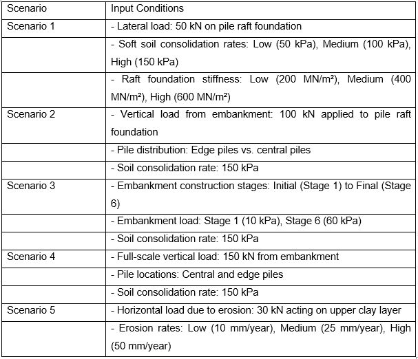
Table 1 Input Conditions for Each Scenario
Scenario 1: Horizontal Displacement in Pile Raft Foundation
The first analysis looks at the horizontal displacement of the pile raft foundation system for the loads acting laterally on this system. The analysis based on the RS2 indicates that horizontal movements are much significant in the relatively soft soil with higher consolidation rate. Pile movements in these areas are large under lateral loads; therefore, the distribution of loads on the raft foundation minimizes the detrimental impacts. Notwithstanding, the effectiveness study shows that increasing the stiffness of the raft foundation leads to the reduction of the overall horizontal displacement thus enhancing the stability of the bridge abutment.
Key findings:
• High soil consolidation rates lead to greater lateral displacements.
• Raft foundation stiffness plays a crucial role in mitigating horizontal displacement.
Scenario 2: Vertical Displacement in Pile Raft Foundation
In this case, the vertical displacements are considered. From analytical results of RS2 software it identified that the vertical displacement is smaller than the horizontal displacements but notable especially when soil conditions are soft. The piles undergo a downward displacement through the load of the embankment and the structural load which passes through the raft foundation to the piles. Intensity of the vertical settlement is higher at the edges of the foundation where piles are installed and the soil does not have adjacent counterpart to support it.
Key findings:
• Vertical displacements are concentrated near the edges of the foundation.
• Increasing the foundation stiffness reduces vertical movement.
Scenario 3: Embankment Initial Stage vs. Embankment Stage 6
This scenario aims at analyzing the evolution process of the embankment. During this stage, the displacement of both piles and soil is quite checked in the sense that major movements have hardly occurred. Moreover, in stage 6 of the embankment construction, both the soil structure and pile displacement are highly affected and altered. The bottom figure depicts the sum impact of the loading – horizontal and vertical deformations rise with each height added to the embankment. This scenario applies the concept of time dependent soil consolidation and the stability of the embankment.
Key findings:
• The initial stage shows minimal displacement.
• Stage 6 reveals substantial horizontal and vertical displacement due to cumulative loading.
Scenario 4: Vertical Settlements
Figure 5 below indicates that settlement is not evenly distributed with the central part of the foundation recording lesser settlement than the outer parts. This is due to the fact that the central area is able to handle more loads owing to the high density of piles. In the process of consolidating the soil it is discovered that the degree of subsequent settlement gradually increases, but does not exceed the admissible in terms of structure. From this, the simulation underscores the significance of controlling the kind of settlement that impacts on the differential movement that enhances the break up of the connecting medium, in this case the abutment of the bridge.
Key findings:
• Central areas of the foundation experience less vertical settlement.
• Differential settlement needs to be minimized to maintain structural integrity.
Scenario 5: Horizontal Movements in the Clay Layer (Soil Erosion)
The last case considered is the influence of soil erosion as a factor affecting horizontal motions in the clay layer. The RS2 analysis shows that with increase in erosion of the soil, the piles horizontal stiffness decreases, particularly in the upper clay layer. These lateral movements are especially more expressed in regions, where the processes of soil erosion are most acute. The results discussed above will stress the need to practice overhead erosion control measures such that excessive lateral movement cannot happen and hence cause a structural failure of the piles and abutment.
Key findings:
• Soil erosion significantly affects lateral stability, increasing horizontal movements.
• Erosion control measures are crucial to ensure long-term stability of the pile foundation system.
.png)
.png)
Table 2 Numerical Results for Each Scenario
3. Summary of Findings from the Results
The findings of this present study from the RS2 simulations are also in consonance with the research objectives formulated at the beginning of this paper and from previous or similar findings such as the one done by M.K. Kelesoglu.
• Simulation results of RS2 was well compared to the empirical data.
• Comparison of real lateral piles deflection with the analysis results indicates that soil consolidation highly influences it.
• The superstructure of pile raft foundations diminished lateral movement in soft ground.
• Lateral stability of piles is significantly influenced by the phenomenon of soil erosion.
References
![]()
EAT80002 Professional Master's Industry Project Report Sample
INTRODUCTION
In this assessment, you are required to prepare a proposal and plan for your allocated industry-linked project. This follows discussions held with your industry and academic supervisors, and your preliminary review of relevant literature. It is expected that you have clarified the problem worth solving to the industry partner and identified an approach or solution that you intend to explore in more depth in the remainder of the semester. This assessment aims to help you develop a value proposition and determine the specific stages and activities that you need to achieve in this project, including the design, research or development work that is required.
DESCRIPTION Your submission should be a document written in the form of a tender or grant proposal that makes the case for the proposed project based on an initial preliminary investigation. It should include statements on:
- The main problem and key questions to address: this should have adequate background information from industry and literature to show that the problem is worth solving to the industry partner and has some validity (it is not simply a whim of the students or supervisors)
- The value, aim and objectives of the project
- The methodological perspectives that underpin your development of the project proposal/plan, including any theory, data required, etc.
- An outline of the methods that you will use to answer the key questions (e.g., experiments, simulations, theoretical modelling, surveys, etc.).
- A plan for the conduct of the project: this should provide a high-level overview of plans for the entire project including key stages and timelines, and a more detailed overview of specific activities for the semester. These should be consistent with the proposed aim and objectives of the project.
- Required resources, including a description of how these resources will be sourced (e.g. access to labs/workshops, funding for projects, software, materials required if known, etc.).
- A general outline of the division of tasks amongst the group members
REQUIRED LENGTH FOR ASSESSMENT COMPONENTS
1. A written proposal (minimum word-count: 2,000 words, excluding references and cover page), preferably sighted and reviewed by your industry project supervisor
2. An outline of the semester plan drafted according to semester weeks and calendar weeks. A Gantt chart is recommended with written milestones and key deliverables
3. Explanations that fully describe activities related to each milestone
4. An outline of group task allocation, drafted according to key milestones and deliverables
Solution
1. Introduction
Energys Australia, one of the world’s first movers in hydrogen energy technology, is committed to popularizing the use of hydrogen energy, making it affordable and easy to obtain. Currently the company has designed a hydrogen fuel cell for use in only stationery application but plans this to be taken to dynamic uses. For this purpose, they must be able to elicit and analyse the fuel cell’s performance under dynamic loading conditions; issues like the stability of the components, vibration and structural integrity come into play. The goal of this project for The Assignment Helpline is to analyse, evaluate the feasibility, material selection and design of some of the component supports and the vibration protection for the hydrogen fuel cell using Ansys software.
2. Background
Fuel cells particularly those that utilises hydrogen are today decried as a clean technology with the capability of generating electricity from hydrogen and oxygen chemicals with water as the only emission. However, due to the structural sensitivity of many of the components to external forces, the practical use of fuel cells, specifically hydrogen fuel cells, in dynamic surroundings (for example, in mobile objects or in zones with high levels of vibrations) still poses certain problems. In dynamic loading cases, vibrations have influence on functions, reliability and durability of the fuel cell (Hassan et al. 2021).
.png)
Figure 1: hydrogen fuel cell generator
(Source: energys.com.au)
Previous research investigated on the vibration analysis conversely the structural support of hydrogen fuel cells which are susceptible to dynamic loads as it is observed in automotive and aerospace manufacturing firms. The key difficulties that can be met in such a project are the following, and this work will focus on the assessment of the current design proposal.
3. Problem Statement
The integrated hydrogen fuel cell system of Energy’s Australia is at the moment not transportable thanks to structural issues regarding its stability and performance under dynamic loads. The need to introduce the fuel cell into a situation where there are varying external forces mean that there is need to undertake a test on part and component supports as well as the vibration protection. Among the technologies, hydrogen fuel cells are promising in renewal energy, especially in stationary uses. Nonetheless, the ability to operate in dynamic environments, for instance in mobile systems or environments affected by vibration is a major challenge (Tang et al. 2021). The currently used hydrogen fuel cell in Energys Australia is fixed in a rigid structure that cannot be moved, and the performance of this fuel cell is likely to be compromised by dynamic loading and or component failure. Dynamic loads which include vibrations, shocks and the likes put mechanical loads on various parts and can cause fatigue, misalignment or even failure of some very vital parts or even an in entire system. In the future when designing vehicles for transportation or portable usage of hydrogen fuel cells, stability and vibration protection will prove to be significant. The failure to meet these challenges might slow down the possibilities of large scale and application of hydrogen fuel cells across various sectors. Hence, this project is very important in detecting, studying, and managing the impacts of dynamic loads on the fuel cell hence guaranteeing its efficiency and durability in different operating conditions.
4. Key Questions
• In what manner do the loading condition changes (vibration, shock) impact the structural design as well as the efficiency of the hydrogen fuel cell?
• What current design constraints are relevant to the numbers and types of components which can be supported and the degree of protection from vibration?
• Which potential design features that ought to be described to overcome these limits are; in what ways can they be adjusted in design or material choice?
• What is the best way to arrange supports and damping mechanisms?
Value: The project opened immense value for Energy’s Australia since they have a hydrogen fuel cell technology accrued employable in dynamic realms. This will extend the usage of their product that makes them to have a new market in transport and other mobile uses.
5. Aim and objectives
Aim
This research project aims at assessing and optimising the component supports and vibration safeguards for the hydrogen fuel cell of Energy’s Australia under dynamic loads.
Objectives
• To perform a comprehensive literature review on hydrogen fuel cells subjected to dynamic loads.
• To model the hydrogen fuel cell in Ansys software and simulate various dynamic loading scenarios.
• To identify critical points of failure or instability in the existing design.
• To propose design modifications to improve component supports and vibration protection.
• To validate the proposed design improvements through further simulations and analysis.
6. Literature Review
The first of these is the collection of background data which is accomplished using a comprehensive literature search. This will encompass researches in areas like the effect of dynamic loads on hydrogen fuel cells; Effects such as vibrations, shocks and any other force which may have an influence on the performance or life cycle of these systems. The review will also look at the current solutions for the protection against vibrations, that is, compositions, pillars as well as the damps. The knowledge from this research will give the framework to reference that can help or hinder, for the further options in the simulation and design aspect of the project.
- Ansys Simulations: Ansys software will be the principal software to analyse the hydrogen fuel cell under different dynamic load conditions. In the actual simulation, there will be significant use of finite element modelling (FEM) to determine stress distribution, deformation and vibration on fuel cell parts. Three specific dynamic load cases will be considered:
1. Harmonic Analysis: This analysis will also determine the effect of sinusoidal loads on the fuel cell since they are some of the most prevalent dynamic loads. Understanding the natural frequencies and resonance characteristic, it will be possible to correlate the fuel cell structural design for vulnerability to destructive vibrations that may cause fatigue or failure.
2. Random Vibration Analysis: This one will simulate environmental conditions as those during transportation or operation in vibrating conditions (Xu et al. 2022). The modal analysis will also include random vibration analysis that will indicate how the various parts of the fuel cell respond to random forces so as to determine the regions that need reinforcement or better damping.
3. Transient Dynamic Analysis: This analysis will assess how the organisation can adjust and respond to changes in the external environment in relation to fuel cell structure. Dynamic analysis of a short duration is important in determining how the fuel cell will behave when exposed to events in which forces are enormous though brief, such as in cases of accidents or sudden motions.
- Design Modification and Optimization: All these results are based on the Ansys simulations; the following step is to offer design changes. This may involve modification of the supports, inclusion of isolators, or the fact that materials used have better damping characteristics. As for each of the modifications proposed, more simulations will have to be made to check their performance. This is an iterative procedure, whereby the design will be modified to suit results elicited from the simulation till the best performance is obtained.
- Validation: However, having developed detailed design changes to the fuel cell design issues investigated in this paper, the improved fuel cell design will go through a validation process. This includes carrying out the final simulations at the dynamic loading conditions in order to check if the enhancements meet the required performance standards. The validation will assure the fuel cell to meet the dynamic loads requirements without exporting structural or efficiency characteristics. If needed, other optimizations will be made to guarantee that the design will be stable and precise under all the pressure expected.
7. Methodological Perspectives
In this project, the theoretical part will be based on the methodological framework that involved model based modelling, simulation and empirical analysis. The four cornerstones of the developing methodology will be drawn and grounded on structural dynamics, vibration analysis and material science.
Key methodologies
- Finite Element Analysis (FEA): Fem Analysis will be carried out using Ansys software where dynamic loading condition will be simulated and the impact of such conditions on the fuel cell components in terms of stress distribution, deformation and vibration will be determined.
- Dynamic Load Analysis: Several dynamic loads will be applied to the fuel cell: harmonic and random vibrations as well as transient dynamic loadings that will mimic operating conditions.
- Material Selection and Analysis: The selection of the materials for components and supports will be according to their way how they can handle dynamic loads with special consideration of damping characteristics and energy absorption.
- Design Optimization: The findings given by the simulations will guide improvement of the designs regarding support structures as well as putting into consideration vibration damper or isolator.
The methods used to address the key questions will include:
- Literature Review: For that purpose, this paragraph aims to provide general information about dynamic loads’ influence on hydrogen fuel cells and the existing approaches to vibration protection.
- Ansys Simulations: The primary assessment tool for the current design and testing change affects. The following dynamic load cases will be considered:
1. Harmonic Analysis: In order to test the nature of the response of the fuel cell to sinusoidal loads.
2. Random Vibration Analysis: For instance, for testing of automobile parts, other parts, or products generally subject to transport, then the environmental conditions to be emulated include the following.
3. Transient Dynamic Analysis: In order to monitor and measure its behaviour in response to sudden forces or shocks.
- Design Modification and Optimization: According to the conclusion of the simulation, suggestions of modification of the design would be made, tried and improved (Qiu et al. 2021).
- Validation: The final design will then be tested for its performance by performing simulations so as to satisfy the measures required under dynamic conditions.
The ways in which the key questions will be addressed will be through theoretical research based on simulations and iterative design. These methods are aimed at assess the overall performance of the hydrogen fuel cell, under dynamic loading condition and recommends and solutions that improves the structure-of-structure and vibration control.
8. Project Plan and Timeline
The project will be conducted over two semesters, with the following stages and timeline
.png)
Figure 2: GANT CHART
9. Required Resources
Software: Ansys software for simulated FEA for data analysis.
Hardware: Access to high-performance computing resources to run complex simulations.
Materials: Specifications of the hydrogen fuel cell components provided by Energy’s Australia.
Lab/Workshop Access: Potential access to vibration testing equipment, if required for experimental validation.
Funding: The project may require funding for software licenses, hardware resources, and material testing, to be coordinated with the university and industry partner.
However, to achieve this and be able to implement this project, there is need to acquire a lot of software and hardware support. The Ansys software will be used as the primary Software for simulation and the Finite element analysis of the hydrogen fuel cell and to analyse the models describing the dynamic states. The simulation information will be processed and analysed to give a reliable end product (Luo et al. 2021). Department of Grids and High-Performance Computing Resources will be crucial in addressing the computational intensity of the simulations for it to produce good results. Energy’s Australia has been securing the specifications of the hydrogen fuel cell components that will be used in the simulations and design change. Also, other unidentified structures that may be used in a laboratory or workshop for testing some array of vibration testing equipment may also be required for experimental purposes to verify some of the simulation findings. Research funding will come in handy when it comes to expenditure like license fees, appropriate hardware and testing of different kinds of materials. These resources will have to be sourced from the university or from the industrial partner with whom the project will have to be coordinated to ensure its success.
10. Division of Tasks
The project will be divided among the group members as follows:
1. Project Management and Coordination: Coordination of the general status of the project and putting into consideration timely delivery of the project.
2. Literature Review and Background Research: Carrying out a literature and writing a review of the specific literature and current practices in the industry.
3. Modelling and Simulation: Developing a model of the fuel cell in Ansys and going through with the simulations.
4. Design and Optimization: Basic Approaches: Simulation analysis and recommendation of changes to the design.
5. Validation and Reporting: Sharing, reviewing the results, finalising the design, and creating the project report and presentation.
11. Conclusion
The objective of this project is to supply Energy’s Australia with a sound strategy for making their hydrogen fuel cell technology applicable to various settings. The project will improve and develop additional supports for specific components, and other forms of vibration mitigation, to advance the use of hydrogen fuel cells in mobile and transportable applications that build on the benefits of clean energy.
References
.png)
MEM601 Engineering Sustainability Report 2 Sample
In this assessment, you will use a strategy process, a methodology and toolsto develop an engineering sustainability strategy and action plan for the engineering and technical operations of an organisation. You should prepare for and approach this task by completing ‘Module 3: Ensuring an Ethical, Responsible and Sustainable Engineering Organisation’ and ‘Module 4: Ensuring Engineering Sustainability Compliance’. To complete this assessment, you will research and examine the following issues for the engineering and technical operations of an organisation of your choice:
1. Describe the currentsustainability situation of the organisation. Thisincludes the:
• Existing engineering sustainability strategy, approach, organisation, practices, objectives, resources and capabilities;
• Ethical and corporate social responsibility and its links to sustainability;
• Business environment and industry conditions; and
• Meaning of engineering sustainability to your selected organisation.
2. Develop the desired future sustainability, stating the:
• Sustainability values, vision and ethical issues;
• Objectives/goalsto be accomplished; and
• The meaning of sustainability to the selected organisation;
3. Develop a management action plan to achieve the desired sustainability that details:
• How, when and who will undertake the actions required to implement the sustainability strategy;
• The management practices and processes that will be implemented to ensure delivery and compliance; and
• How to engage with stakeholders, set goals and commitments, establish systems and processes, track progress, communicate actions and meet expectations.
Solution
Introduction
On a global scale, engineering firms are adopting sustainable practices in order to protect the natural environment. Being a technology and engineering firm, Commonwealth Engineers has made successful strides towards the proper implementation of green infrastructure in different types of public work projects. A structured and reviewed action plan and strategy are necessary to evolve and improve the existing sustainability strategy of the company. Here, the current sustainability initiatives of the company, the desired future sustainability state and a detailed action plan will be provided so that the existing sustainability initiatives of the company are improved.
Existing Sustainability Situation
Commonwealth Engineers has made some significant progress in terms of incorporating some adequate green infrastructure within their public work projects (Commonwealthengineers, 2024). Green infrastructure mainly highlights environment-friendly designs capable of mimicking natural ecosystems which can capture reduced waste, energy consumption, costs and others. The company also try to provide low-environment impact solutions in infrastructure. Additionally, environmental protection and remediation can also be described as one of the major sustainability initiatives of the company (Commonwealthengineers, 2024). Remediation is crucial in terms of mitigating the adverse environmental influence of different engineering projects, specifically ecosystem disruption and pollution. After investing in ecological remediation, Commonwealth Engineers properly participate in the process of reducing pollutants and preserving habitats.
Furthermore, the company is also responsible for conducting several energy audits in order to identify inefficiencies while optimising proper energy usage in different projects (Commonwealthengineers, 2024). After conducting a proper life-cycle cost analysis, it is possible for the company to ensure that the economic costs are minimised and the environmental impacts are managed. It is possible for the company to get economic benefits after successfully adopting the reduced energy consumption aspects. The inclusion of a life-cycle assessment is setting a strong foundation from the perspective of extensive resource efficiency and management of sustainability objectives (Al-Breiki & Bicer, 2021). The expertise of the company for the Assignment Help in terms of green energy and green infrastructure is responsible for shaping and improving its sustainability practices.
Desired Future State in Sustainability
The desired future state and vision of Commonwealth Engineers is to become a leading sustainable engineering company. The process involves deepening green infrastructure, advancing environmental remediation efforts, extending renewable energy programs, and improving methods for waste reduction (Liu et al., 2024). Under the ideal future, Commonwealth Engineers will try to implement green infrastructure in all important projects and learn from the experience of ongoing deployments to further advance the state-of-the-art ecological design methodologies in a wide range of infrastructure projects. That is associated with the creation of robust urban habitats, improving biodiversity, decreasing flooding in urban areas through the application of sustainable drainage systems, and making green roofs and rainwater catchments the norm (Nielsen et al., 2021).
Through the expansion of remediation activities, Commonwealth Engineers would emerge as a zero-impact engineering company that is committed to restoring natural habitats to their pre-existing state or better upon completion of projects. This intent shall extend to include the application of new restoration methodologies, including phytoremediation, coupled with increased collaboration with environmental organisations along with on-site species diversification (Narayanan & Ma, 2022). The desired state for Commonwealth Engineers is to develop distinct metrics related to ecosystem restoration outcomes, exhibiting quantifiable environmental benefits. Additionally, energy audits for the company will need to expand to incorporate a specific transition strategy toward renewable energy. Future work for the company will strive towards carbon neutrality by using on-site solar, wind, and even geothermal energy during its process and project sites (Wu et al., 2022). Their contribution will include on-site renewable energy installations and sourcing materials with a reduced carbon footprint. Lastly, Commonwealth Engineers will try to minimise material waste by maximising a circular economy philosophy by reusing and recycling materials wherever feasible. This includes a future vision for designing projects to be deconstructed at the end of the life of that structure, allowing materials to be repurposed (Obi et al., 2021). Waste and recycling metrics will be rigorously tracked by Commonwealth Engineers to ensure the highest levels of transparency and accountability. The company will need to be working toward a 50% reduction in landfill contributions over the coming decade.
Management Action Plan
The road to the future desired state calls for the action plan of management, which at Commonwealth Engineers covers updates of policy, resource allocations, and training of the team. An action plan is highlighted below for each strategic component, through which the envisioned sustainability goals are achieved.
.png)
.png)
.png)
.png)
.png)
.png)
.png)
Table 1: Management action plan
(Source: Self-constructed)
Conclusion
After implementing a proper sustainability strategy and action plan, it is possible for Commonwealth Engineers will be able to establish itself as one of the main leaders of sustainable engineering. With the help of proper policies, proper investments must be made in robust community relationships, employee education and similar aspects so that the existing sustainable options of the company are increased.
References
.png)
- Assignment - Child Care
- Assignment - Mathematics
- Assignment - Accounting
- Assignment - Auditing
- Assignment - Biology
- Assignment - Law
- Assignment - Management
- Assignment - Nursing
- Assignment - Finance
- Assignment - Computer Science and IT
- Assignment - Humanities
- Assignment - Economics
- Assignment - Statistics
- Assignment - Architecture
- Assignment - Engineering
- Assignment - cookery
- Assignment - Marketing
- Case Study - Chemistry
- Case Study - Accounting
- Case Study - Law
- Case Study - Management
- Case Study - Nursing
- Case Study - Finance
- Case Study - Computer Science and IT
- Case Study - Engineering
- Case Study - Economics
- Case Study - Biology
- Case Study - Auditing
- Case Study - Marketing
- Case Study - Project Management
- Coursework - Diploma
- Coursework - Accounting
- Coursework - Auditing
- Coursework - Biology
- Coursework - Management
- Coursework - Nursing
- Coursework - Finance
- Coursework - Computer Science and IT
- Coursework - Engineering
- Coursework - Humanities
- Coursework - Child Care
- Coursework - Project Management
- Coursework - Economics
- Coursework - Cookery
- Coursework - Law
- Dissertation - Accounting
- Dissertation - Auditing
- Dissertation - Biology
- Dissertation - Law
- Dissertation - Management
- Dissertation - Nursing
- Dissertation - Finance
- Dissertation - Computer Science and IT
- Dissertation - Humanities
- Dissertation - Economics
- Essay - Politics
- Essay - Childcare
- Essay - Accounting
- Essay - Biology
- Essay - Law
- Essay - Management
- Essay - Nursing
- Essay - Computer Science and IT
- Essay - Humanities
- Essay - Economics
- Essay - Auditing
- Essay - Engineering
- Essay - Architecture
- Essay - Finance
- Essay - Science
- Essay - Marketing
- Programming - Computer Science and IT
- Reports - Management
- Reports - Computer Science and IT
- Reports - Project Management
- Reports - Marketing
- Reports - Nursing
- Reports - Engineering
- Reports - Accounting
- Reports - Humanities
- Reports - Finance
- Reports - Architecture
- Reports - Biology
- Reports - Economics
- Reports - Childcare
- Reports - Law
- Research - Accounting
- Research - Auditing
- Research - Biology
- Research - Law
- Research - Management
- Research - Nursing
- Research - Finance
- Research - Computer Science and IT
- Research - Science
- Research - Engineering
- Research - Humanities
- Research - Economics
- Research - Project Management
- Research - Statistics
- Research - Architecture
- Research - Marketing
- Thesis Writing - Computer Science and IT
- Thesis Writing - Engineering
- Thesis Writing - Biology
- Thesis Writing - Finance
- Thesis Writing - Humanities
- Thesis Writing - Auditing
- Thesis Writing - Economics
- Thesis Writing - Law
- Thesis Writing - Nursing
- Thesis Writing - Accounting
- Thesis Writing - Architecture


.png)
~5.png)
.png)
~1.png)


.png)