Reports
MEM601 Engineering Sustainability Report 2 Sample
In this assessment, you will use a strategy process, a methodology and toolsto develop an engineering sustainability strategy and action plan for the engineering and technical operations of an organisation. You should prepare for and approach this task by completing ‘Module 3: Ensuring an Ethical, Responsible and Sustainable Engineering Organisation’ and ‘Module 4: Ensuring Engineering Sustainability Compliance’. To complete this assessment, you will research and examine the following issues for the engineering and technical operations of an organisation of your choice:
1. Describe the currentsustainability situation of the organisation. Thisincludes the:
• Existing engineering sustainability strategy, approach, organisation, practices, objectives, resources and capabilities;
• Ethical and corporate social responsibility and its links to sustainability;
• Business environment and industry conditions; and
• Meaning of engineering sustainability to your selected organisation.
2. Develop the desired future sustainability, stating the:
• Sustainability values, vision and ethical issues;
• Objectives/goalsto be accomplished; and
• The meaning of sustainability to the selected organisation;
3. Develop a management action plan to achieve the desired sustainability that details:
• How, when and who will undertake the actions required to implement the sustainability strategy;
• The management practices and processes that will be implemented to ensure delivery and compliance; and
• How to engage with stakeholders, set goals and commitments, establish systems and processes, track progress, communicate actions and meet expectations.
Solution
Introduction
On a global scale, engineering firms are adopting sustainable practices in order to protect the natural environment. Being a technology and engineering firm, Commonwealth Engineers has made successful strides towards the proper implementation of green infrastructure in different types of public work projects. A structured and reviewed action plan and strategy are necessary to evolve and improve the existing sustainability strategy of the company. Here, the current sustainability initiatives of the company, the desired future sustainability state and a detailed action plan will be provided so that the existing sustainability initiatives of the company are improved.
Existing Sustainability Situation
Commonwealth Engineers has made some significant progress in terms of incorporating some adequate green infrastructure within their public work projects (Commonwealthengineers, 2024). Green infrastructure mainly highlights environment-friendly designs capable of mimicking natural ecosystems which can capture reduced waste, energy consumption, costs and others. The company also try to provide low-environment impact solutions in infrastructure. Additionally, environmental protection and remediation can also be described as one of the major sustainability initiatives of the company (Commonwealthengineers, 2024). Remediation is crucial in terms of mitigating the adverse environmental influence of different engineering projects, specifically ecosystem disruption and pollution. After investing in ecological remediation, Commonwealth Engineers properly participate in the process of reducing pollutants and preserving habitats.
Furthermore, the company is also responsible for conducting several energy audits in order to identify inefficiencies while optimising proper energy usage in different projects (Commonwealthengineers, 2024). After conducting a proper life-cycle cost analysis, it is possible for the company to ensure that the economic costs are minimised and the environmental impacts are managed. It is possible for the company to get economic benefits after successfully adopting the reduced energy consumption aspects. The inclusion of a life-cycle assessment is setting a strong foundation from the perspective of extensive resource efficiency and management of sustainability objectives (Al-Breiki & Bicer, 2021). The expertise of the company for the Assignment Help in terms of green energy and green infrastructure is responsible for shaping and improving its sustainability practices.
Desired Future State in Sustainability
The desired future state and vision of Commonwealth Engineers is to become a leading sustainable engineering company. The process involves deepening green infrastructure, advancing environmental remediation efforts, extending renewable energy programs, and improving methods for waste reduction (Liu et al., 2024). Under the ideal future, Commonwealth Engineers will try to implement green infrastructure in all important projects and learn from the experience of ongoing deployments to further advance the state-of-the-art ecological design methodologies in a wide range of infrastructure projects. That is associated with the creation of robust urban habitats, improving biodiversity, decreasing flooding in urban areas through the application of sustainable drainage systems, and making green roofs and rainwater catchments the norm (Nielsen et al., 2021).
Through the expansion of remediation activities, Commonwealth Engineers would emerge as a zero-impact engineering company that is committed to restoring natural habitats to their pre-existing state or better upon completion of projects. This intent shall extend to include the application of new restoration methodologies, including phytoremediation, coupled with increased collaboration with environmental organisations along with on-site species diversification (Narayanan & Ma, 2022). The desired state for Commonwealth Engineers is to develop distinct metrics related to ecosystem restoration outcomes, exhibiting quantifiable environmental benefits. Additionally, energy audits for the company will need to expand to incorporate a specific transition strategy toward renewable energy. Future work for the company will strive towards carbon neutrality by using on-site solar, wind, and even geothermal energy during its process and project sites (Wu et al., 2022). Their contribution will include on-site renewable energy installations and sourcing materials with a reduced carbon footprint. Lastly, Commonwealth Engineers will try to minimise material waste by maximising a circular economy philosophy by reusing and recycling materials wherever feasible. This includes a future vision for designing projects to be deconstructed at the end of the life of that structure, allowing materials to be repurposed (Obi et al., 2021). Waste and recycling metrics will be rigorously tracked by Commonwealth Engineers to ensure the highest levels of transparency and accountability. The company will need to be working toward a 50% reduction in landfill contributions over the coming decade.
Management Action Plan
The road to the future desired state calls for the action plan of management, which at Commonwealth Engineers covers updates of policy, resource allocations, and training of the team. An action plan is highlighted below for each strategic component, through which the envisioned sustainability goals are achieved.
.png)
.png)
.png)
.png)
.png)
.png)
.png)
Table 1: Management action plan
(Source: Self-constructed)
Conclusion
After implementing a proper sustainability strategy and action plan, it is possible for Commonwealth Engineers will be able to establish itself as one of the main leaders of sustainable engineering. With the help of proper policies, proper investments must be made in robust community relationships, employee education and similar aspects so that the existing sustainable options of the company are increased.
References
.png)
Assignment
EGH454 Harmonic Analysis of Solar System Assignment 2 Sample
Your Task
Single line diagram of the system. Your task is to perform the following two investigations on the system, as briefly outlined in the Problem, and then comprehensibly document your findings: Task 1.
Task 3.
Comprehensively document your findings in the form of a neat, concise paper: The paper should have a maximum eight (8) pages and use the IEEE two-column conference paper template, which will be provided. Make good use of clear wellconstructed images and graphics to aid in your reporting. This paper should be presented in a PDF format.
Solution
Abstract: The connection of renewable energy sources especially solar photovoltaic (PV) systems presents issues about power quality issues; predominantly harmonic distortions resulting from power electronic converters. This work assesses the predicted lifetime of key pieces of equipment – three-phase induction motors and transformers – when exposed to voltage harmonics at the 33 kV PCC. Using harmonic voltage data up to the 40th harmonic of the induction motor and its corresponding ambient and rated temperatures, the useful life of the motor is estimated to be about 33.093 years, and the transformer, about 35.11 years. This work has revealed the significance of proper harmonic compensating measures for increasing power system reliability and service life of electrical equipment in RE systems. This overview also points out that the use of harmonic filters as well as the identification of more effective maintenance schedules can prevent the negative consequences of harmonics resulting in longer equipment life. It is on this premise for Assignment Help that this research seeks to stress the importance of constant vigilance and control of power quality in electrical systems as the dependency on renewable energy sources increases.
The continuous incorporation of Renewable Energy Sources, especially Solar Photovoltaic systems, into utility power systems has led to new problems concerning power quality and gadget durability. Many of these systems incorporate power electronic converters that produce harmonic distortions that may degrade the load equipment's performance and life, including three-phase induction motors and transformers. Potential negative effects resulting from voltage harmonics indicated by the THD include increased temperature, overheating, losses, differential dripping, and earlier failures on the electrical equipment.
This is due to the fact that the reliability and efficiency of a power system depends on the knowledge regarding the expected life of such equipment in the presence of these harmonics. This analysis includes going up to the 40th harmonic and including the effects of temperature in the lifespan models. Through the use of ambient temperature, rated temperature, and constants relevant to the specific equipment, it is possible to gain valuable information on the useful life of these parts. The result can be used to guide design considerations and management tactics to minimize the harmonic effects to strengthen electrical systems during the transition phase towards renewable energy systems.
II. Task 1
a)
.png)
Figure 1: 40th Harmonic Content of the Voltage Plot
(Source: Acquired from MATLAB)
The image gives an interface view of an FFT (Fast Fourier Transform) analyzer, a common application in signal and vibration analysis [1]. Parameters of the structure with links, signal type, start time, number of orders, window type, and reference frequency can be set in the interface. It displays two main plots: The upper plot represents the time domain signal waveform, and the lower plot is the FFT result where on the x-axis there are harmonic orders,and, on the y-axis, there is magnitude either in linear or in DB. There are also options to perform an FFT calculation on an input and export the data in the working interface. Some key parameters like the power spectra density and Total Harmonic Distortion (THD) are demonstrated and the first frequency component is depicted in the lower plot.
.png)
Figure 2: 40th Harmonic Content of the Current Plot
(Source: Acquired from MATLAB)
The second FFT analyzer, as seen in Figure 2, has the same layout as the previous one but with slightly different signals. It makes it possible for the user to input parameters such as signal type (in this case a current signal), dimension, start time, number of orders, and window type. The figure on the top is the time-domain plot of the signal, where changes in magnitude over a time scale are indicated whereas the figure at the bottom part is the frequency-domain results where on the x-axis are the harmonic orders and on the y-axis are the amplitude or magnitude. Key details such as the fundamental frequency (34.81 Hz) and total harmonic distortion (THD: 6.64%) are visible. The user is also able to compute FFT and then export the results [2]. The frequency-domain plot emphasizes areas of a signal containing high-energy harmonic components to facilitate frequency analysis.
b)
![]()
Figure 3: Expected Life for Equipment Calculation
(Source: Acquired from MATLAB)
It takes about 33.09 years to complete its [motor’s] life cycle than to complete the life cycle of a three-phase induction motor which has been projected to live 24.91 years longer at 35.11 years. These figures are based on voltage harmonic distortions that affect the aging of electrical equipment as is well known. Thus, the major reason for the induction motor’s relatively shorter lifespan is attributed to thermal implication effects heightened by thermal stresses and harmonic-induced losses. On the other hand, the transformer has a more favorable design; the circuit can provide the equipment with more powerful anti-interference capabilities to work under similar conditions as above and has a higher expected service life. Consequently, electrical utilities with both HVDC and renewable energy interfaces require measurement and analysis of harmonic contents for risk mitigation and improvement of critical components' reliability. Allowing harmonic distortions when used to be successful for operators to get longer equipment lifespan as well as make the power transmission in the grid far more efficient and stable.
III. Task 2
.png)
(Source: Acquired from MATLAB)
The image presented is a Simulink model structured for a power system probably for simulating an inverter or a solar power system. The model consists of squares that symbolize various elements of the model. At the highest level of the model measurement blocks for voltages, currents, and powers can be observed. From there the main system diagram starts with an area for a grid at the far left, a 3.3 kV feeder, filters, and an inverter transformer. The diagram is followed with different LCL filters and chokes which roughly suggest that the system has a harmonic filtering stage. The system also consists of devices such as a ‘3MW Solar Inverter 500Hz’ which can be understood that the model is probably emulating power conversion through an inverter from solar energy. A filter for both 420 Hz and 600 Hz is presented towards the end to show that the circuit has been designed to target certain harmonic frequencies. The entire setup seems to be employed in a simulated grid interconnected photovoltaic power generation system that would give a demonstration of the electric flow from grid interconnection, through transformer and inverter filtering stages with multiple filter stages.
a)
.png)
Figure 5: 40th Harmonic Content of the Voltage Plot after Connecting Filtering Block
(Source: Acquired from MATLAB)
The picture depicts the FFT Analyzer which is the interface of a software application related to signal analysis. The waveform on the right-hand side is a time-domain waveform or signal – a sinusoidal waveform captured in the vertical axis overtime on the horizontal axis at a small interval of time. The bottom plot of the signal is formed as a frequency spectrum which indicates the magnitude of the different harmonic components at different frequencies. The points of interaction of the device also enable users to select the signal type, input limit frequencies, harmonic order, and compute FFT. Specific parameters include the basic frequency, the overall harmonic distortion, and a bar that indicates the level of each of the first-order harmonics. Of most importance is that the user can export the results at the end of the computation process.
.png)
Figure 6: 40th Harmonic Content of the Current Plot after Connecting Filtering Block
(Source: Acquired from MATLAB)
The first plot represents an ideal sinusoid waveform in the time division: amplitude is shown on the y-axis and time is represented on the x-axis; the record has been made during a short period. The lower plot gives the frequency domain view and shows the amplitudes of the harmonics of the signal. Currently, as the structure with links, the signal type and the frequency parameters can be changed in the analyzer interface. In particular, it calculates the first prominent harmonic, the measured distortion in terms of THD, and the desired order of harmonics with an additional feature allowing downloading results.
b)
![]()
Figure 7: The Expected Life for the Equipment
(Source: Acquired from MATLAB)
The reliability analysis also reveals that the expected life of the three-phase induction motor is 34.00 years, and the expected life of the three-phase transformer is 34.07 years approximately. This assessment reduces the life expectancy of the pieces of equipment into account owing to harmonic distortions under certain conditions of ambient as well as rated temperatures, and the Total Harmonic Distortion (THD) of the voltage supply [3]. The two pieces of equipment are exposed to operating conditions, which include stress due to voltage harmonics. The slight variation of expected life means that while both the devices deteriorate due to the environment and electrical factors, the transformer was found to be slightly more resistant probably due to design and operation constraints. From these outcomes, it may be concluded that harmonic content levels should be taken into account when estimating equipment lifespan; hence, conditions for efficient filtering and design should be provided for improving the reliability of electrical systems in renewable energy facilities.
IV. Conclusion
Therefore, using the expected lifespan of a three-phase induction motor and transformer to control the aging of equipment in renewable power systems, the study established the effects of voltage harmonic distortions. Since the induction motor is predicted to last for approximately 33.09 years while the transformer is 35.11 years, it can be seen that both are prone to problems with harmonic content and thermal stress. These findings indicate that harmonic control methods including the utilization of tuned filters should be used to avoid the impacts of voltage harmonics on the efficiency and durability of equipment. Increasing global complexity of interconnecting renewable energy power sources such as solar PV systems, it will be crucial to analyze the synergies between the harmonic distortions and the behaviors of related equipment to maintain the reliability and efficiency of power systems. Moreover, applying tuning to both torsional and lightly damped systems is considered mandatory for stakeholders of advanced equipment to maintain constant monitoring and solve the problems connected with harmonics and thermal regulation. Through proper management of power quality issues, it becomes feasible to guarantee the increased durability of fundamental electric parts; this will enable the coaxing of more effective energy solutions as well as strengthening the stability of the electrical power network. This will in turn enhance electric energy availability and reliability in the organization, hence, enhance the economic outcome of a power system operator.
References
.png)
Reports
EAT80002 Professional Master's Industry Project Report Sample
INTRODUCTION
In this assessment, you are required to prepare a proposal and plan for your allocated industry-linked project. This follows discussions held with your industry and academic supervisors, and your preliminary review of relevant literature. It is expected that you have clarified the problem worth solving to the industry partner and identified an approach or solution that you intend to explore in more depth in the remainder of the semester. This assessment aims to help you develop a value proposition and determine the specific stages and activities that you need to achieve in this project, including the design, research or development work that is required.
DESCRIPTION Your submission should be a document written in the form of a tender or grant proposal that makes the case for the proposed project based on an initial preliminary investigation. It should include statements on:
- The main problem and key questions to address: this should have adequate background information from industry and literature to show that the problem is worth solving to the industry partner and has some validity (it is not simply a whim of the students or supervisors)
- The value, aim and objectives of the project
- The methodological perspectives that underpin your development of the project proposal/plan, including any theory, data required, etc.
- An outline of the methods that you will use to answer the key questions (e.g., experiments, simulations, theoretical modelling, surveys, etc.).
- A plan for the conduct of the project: this should provide a high-level overview of plans for the entire project including key stages and timelines, and a more detailed overview of specific activities for the semester. These should be consistent with the proposed aim and objectives of the project.
- Required resources, including a description of how these resources will be sourced (e.g. access to labs/workshops, funding for projects, software, materials required if known, etc.).
- A general outline of the division of tasks amongst the group members
REQUIRED LENGTH FOR ASSESSMENT COMPONENTS
1. A written proposal (minimum word-count: 2,000 words, excluding references and cover page), preferably sighted and reviewed by your industry project supervisor
2. An outline of the semester plan drafted according to semester weeks and calendar weeks. A Gantt chart is recommended with written milestones and key deliverables
3. Explanations that fully describe activities related to each milestone
4. An outline of group task allocation, drafted according to key milestones and deliverables
Solution
1. Introduction
Energys Australia, one of the world’s first movers in hydrogen energy technology, is committed to popularizing the use of hydrogen energy, making it affordable and easy to obtain. Currently the company has designed a hydrogen fuel cell for use in only stationery application but plans this to be taken to dynamic uses. For this purpose, they must be able to elicit and analyse the fuel cell’s performance under dynamic loading conditions; issues like the stability of the components, vibration and structural integrity come into play. The goal of this project for The Assignment Helpline is to analyse, evaluate the feasibility, material selection and design of some of the component supports and the vibration protection for the hydrogen fuel cell using Ansys software.
2. Background
Fuel cells particularly those that utilises hydrogen are today decried as a clean technology with the capability of generating electricity from hydrogen and oxygen chemicals with water as the only emission. However, due to the structural sensitivity of many of the components to external forces, the practical use of fuel cells, specifically hydrogen fuel cells, in dynamic surroundings (for example, in mobile objects or in zones with high levels of vibrations) still poses certain problems. In dynamic loading cases, vibrations have influence on functions, reliability and durability of the fuel cell (Hassan et al. 2021).
.png)
Figure 1: hydrogen fuel cell generator
(Source: energys.com.au)
Previous research investigated on the vibration analysis conversely the structural support of hydrogen fuel cells which are susceptible to dynamic loads as it is observed in automotive and aerospace manufacturing firms. The key difficulties that can be met in such a project are the following, and this work will focus on the assessment of the current design proposal.
3. Problem Statement
The integrated hydrogen fuel cell system of Energy’s Australia is at the moment not transportable thanks to structural issues regarding its stability and performance under dynamic loads. The need to introduce the fuel cell into a situation where there are varying external forces mean that there is need to undertake a test on part and component supports as well as the vibration protection. Among the technologies, hydrogen fuel cells are promising in renewal energy, especially in stationary uses. Nonetheless, the ability to operate in dynamic environments, for instance in mobile systems or environments affected by vibration is a major challenge (Tang et al. 2021). The currently used hydrogen fuel cell in Energys Australia is fixed in a rigid structure that cannot be moved, and the performance of this fuel cell is likely to be compromised by dynamic loading and or component failure. Dynamic loads which include vibrations, shocks and the likes put mechanical loads on various parts and can cause fatigue, misalignment or even failure of some very vital parts or even an in entire system. In the future when designing vehicles for transportation or portable usage of hydrogen fuel cells, stability and vibration protection will prove to be significant. The failure to meet these challenges might slow down the possibilities of large scale and application of hydrogen fuel cells across various sectors. Hence, this project is very important in detecting, studying, and managing the impacts of dynamic loads on the fuel cell hence guaranteeing its efficiency and durability in different operating conditions.
4. Key Questions
• In what manner do the loading condition changes (vibration, shock) impact the structural design as well as the efficiency of the hydrogen fuel cell?
• What current design constraints are relevant to the numbers and types of components which can be supported and the degree of protection from vibration?
• Which potential design features that ought to be described to overcome these limits are; in what ways can they be adjusted in design or material choice?
• What is the best way to arrange supports and damping mechanisms?
Value: The project opened immense value for Energy’s Australia since they have a hydrogen fuel cell technology accrued employable in dynamic realms. This will extend the usage of their product that makes them to have a new market in transport and other mobile uses.
5. Aim and objectives
Aim
This research project aims at assessing and optimising the component supports and vibration safeguards for the hydrogen fuel cell of Energy’s Australia under dynamic loads.
Objectives
• To perform a comprehensive literature review on hydrogen fuel cells subjected to dynamic loads.
• To model the hydrogen fuel cell in Ansys software and simulate various dynamic loading scenarios.
• To identify critical points of failure or instability in the existing design.
• To propose design modifications to improve component supports and vibration protection.
• To validate the proposed design improvements through further simulations and analysis.
6. Literature Review
The first of these is the collection of background data which is accomplished using a comprehensive literature search. This will encompass researches in areas like the effect of dynamic loads on hydrogen fuel cells; Effects such as vibrations, shocks and any other force which may have an influence on the performance or life cycle of these systems. The review will also look at the current solutions for the protection against vibrations, that is, compositions, pillars as well as the damps. The knowledge from this research will give the framework to reference that can help or hinder, for the further options in the simulation and design aspect of the project.
- Ansys Simulations: Ansys software will be the principal software to analyse the hydrogen fuel cell under different dynamic load conditions. In the actual simulation, there will be significant use of finite element modelling (FEM) to determine stress distribution, deformation and vibration on fuel cell parts. Three specific dynamic load cases will be considered:
1. Harmonic Analysis: This analysis will also determine the effect of sinusoidal loads on the fuel cell since they are some of the most prevalent dynamic loads. Understanding the natural frequencies and resonance characteristic, it will be possible to correlate the fuel cell structural design for vulnerability to destructive vibrations that may cause fatigue or failure.
2. Random Vibration Analysis: This one will simulate environmental conditions as those during transportation or operation in vibrating conditions (Xu et al. 2022). The modal analysis will also include random vibration analysis that will indicate how the various parts of the fuel cell respond to random forces so as to determine the regions that need reinforcement or better damping.
3. Transient Dynamic Analysis: This analysis will assess how the organisation can adjust and respond to changes in the external environment in relation to fuel cell structure. Dynamic analysis of a short duration is important in determining how the fuel cell will behave when exposed to events in which forces are enormous though brief, such as in cases of accidents or sudden motions.
- Design Modification and Optimization: All these results are based on the Ansys simulations; the following step is to offer design changes. This may involve modification of the supports, inclusion of isolators, or the fact that materials used have better damping characteristics. As for each of the modifications proposed, more simulations will have to be made to check their performance. This is an iterative procedure, whereby the design will be modified to suit results elicited from the simulation till the best performance is obtained.
- Validation: However, having developed detailed design changes to the fuel cell design issues investigated in this paper, the improved fuel cell design will go through a validation process. This includes carrying out the final simulations at the dynamic loading conditions in order to check if the enhancements meet the required performance standards. The validation will assure the fuel cell to meet the dynamic loads requirements without exporting structural or efficiency characteristics. If needed, other optimizations will be made to guarantee that the design will be stable and precise under all the pressure expected.
7. Methodological Perspectives
In this project, the theoretical part will be based on the methodological framework that involved model based modelling, simulation and empirical analysis. The four cornerstones of the developing methodology will be drawn and grounded on structural dynamics, vibration analysis and material science.
Key methodologies
- Finite Element Analysis (FEA): Fem Analysis will be carried out using Ansys software where dynamic loading condition will be simulated and the impact of such conditions on the fuel cell components in terms of stress distribution, deformation and vibration will be determined.
- Dynamic Load Analysis: Several dynamic loads will be applied to the fuel cell: harmonic and random vibrations as well as transient dynamic loadings that will mimic operating conditions.
- Material Selection and Analysis: The selection of the materials for components and supports will be according to their way how they can handle dynamic loads with special consideration of damping characteristics and energy absorption.
- Design Optimization: The findings given by the simulations will guide improvement of the designs regarding support structures as well as putting into consideration vibration damper or isolator.
The methods used to address the key questions will include:
- Literature Review: For that purpose, this paragraph aims to provide general information about dynamic loads’ influence on hydrogen fuel cells and the existing approaches to vibration protection.
- Ansys Simulations: The primary assessment tool for the current design and testing change affects. The following dynamic load cases will be considered:
1. Harmonic Analysis: In order to test the nature of the response of the fuel cell to sinusoidal loads.
2. Random Vibration Analysis: For instance, for testing of automobile parts, other parts, or products generally subject to transport, then the environmental conditions to be emulated include the following.
3. Transient Dynamic Analysis: In order to monitor and measure its behaviour in response to sudden forces or shocks.
- Design Modification and Optimization: According to the conclusion of the simulation, suggestions of modification of the design would be made, tried and improved (Qiu et al. 2021).
- Validation: The final design will then be tested for its performance by performing simulations so as to satisfy the measures required under dynamic conditions.
The ways in which the key questions will be addressed will be through theoretical research based on simulations and iterative design. These methods are aimed at assess the overall performance of the hydrogen fuel cell, under dynamic loading condition and recommends and solutions that improves the structure-of-structure and vibration control.
8. Project Plan and Timeline
The project will be conducted over two semesters, with the following stages and timeline
.png)
Figure 2: GANT CHART
9. Required Resources
Software: Ansys software for simulated FEA for data analysis.
Hardware: Access to high-performance computing resources to run complex simulations.
Materials: Specifications of the hydrogen fuel cell components provided by Energy’s Australia.
Lab/Workshop Access: Potential access to vibration testing equipment, if required for experimental validation.
Funding: The project may require funding for software licenses, hardware resources, and material testing, to be coordinated with the university and industry partner.
However, to achieve this and be able to implement this project, there is need to acquire a lot of software and hardware support. The Ansys software will be used as the primary Software for simulation and the Finite element analysis of the hydrogen fuel cell and to analyse the models describing the dynamic states. The simulation information will be processed and analysed to give a reliable end product (Luo et al. 2021). Department of Grids and High-Performance Computing Resources will be crucial in addressing the computational intensity of the simulations for it to produce good results. Energy’s Australia has been securing the specifications of the hydrogen fuel cell components that will be used in the simulations and design change. Also, other unidentified structures that may be used in a laboratory or workshop for testing some array of vibration testing equipment may also be required for experimental purposes to verify some of the simulation findings. Research funding will come in handy when it comes to expenditure like license fees, appropriate hardware and testing of different kinds of materials. These resources will have to be sourced from the university or from the industrial partner with whom the project will have to be coordinated to ensure its success.
10. Division of Tasks
The project will be divided among the group members as follows:
1. Project Management and Coordination: Coordination of the general status of the project and putting into consideration timely delivery of the project.
2. Literature Review and Background Research: Carrying out a literature and writing a review of the specific literature and current practices in the industry.
3. Modelling and Simulation: Developing a model of the fuel cell in Ansys and going through with the simulations.
4. Design and Optimization: Basic Approaches: Simulation analysis and recommendation of changes to the design.
5. Validation and Reporting: Sharing, reviewing the results, finalising the design, and creating the project report and presentation.
11. Conclusion
The objective of this project is to supply Energy’s Australia with a sound strategy for making their hydrogen fuel cell technology applicable to various settings. The project will improve and develop additional supports for specific components, and other forms of vibration mitigation, to advance the use of hydrogen fuel cells in mobile and transportable applications that build on the benefits of clean energy.
References
.png)
Reports
ENGR9710B Industry Honours Thesis Report Sample
The report must adhere to the page limit, which is 4 pages (i.e. 4 A4 pages) with single-line spacing. Additional contents or supplementary information can be included in an appendix.
The appendix will not contribute to the overall assessment but can be used to provide further details if necessary.
Assessment Criteria
The total mark for this assessment is 10%. This assessment includes the following key criteria along with the relevant sub-criteria:
Reporting Results and Data
- Clear and logical presentation of relevant system(s) and results.
- Effective use of tables, graphs, and figures to convey data.
- Presentation of results supporting research objectives
Data Analysis and Interpretation
- Critical, accurate and thorough data analysis aligned with research objectives,
- Use of qualitative or quantitative methods, where appropriate
Integration and Relevance
- Results are well-integrated into the overall context of the research project.
- Clear relevance of results to research objectives and hypotheses.
- A coherent link with research objectives and expected outcomes over a range of scenarios/comparisons to demonstrate the effectiveness of the proposed method.
Integration and Relevance
- Effective use of formatting, presentation style, and high-quality visuals (graphs, tables, figures) that are clear, well-integrated and easy to interpret.
- Adherence to formatting guidelines, including page limits, and the use of
professional language and grammar.
- All figures and visuals should ensure that information such as axes labels, legends, and text are large enough to be easily read.
Solution
Brief Introduction
This project aims at studying horizontal displacements of bridge abutments on piles in soft soils media with the aid of RS2 software. The first research question is to make explicit the consensus on the behavior of pile foundations when exposed to lateral load and ground conditions of soft soil in respect to soil consolidation, pile raft foundations, and erosion. The RS2 software developed by Rocscience is used in the calculation and modeling of behaviour of the existing soil structure interaction. The anticipated findings include assessing the degree to which RS2 results compare with findings from prior research, especially M.K. Kelesoglu [1], and determining the similarity of other empirical findings from the similar context.
1. System Description
The system under analysis for the Assignment Helpline is a numerical model of a bridge abutment bearing on piles founded in soft soil. This system aims at establishing the lateral movement of piles as a result of load factors that include traffic loads and any other environmental forces. Both the RS2 software is used for the pile/soil interaction where required parameterssuch as consolidation, erosion, behaviour of pile raft foundation, etc. To prove the versatility of the conceptual approach and show the interconnectedness of such factors as soil consolidation, pile raft foundation, and erosion, figure 1 is used. By so doing, the overriding parameters that have to do with soft soil character and pile structural behavior are incorporated.
.png)
Figure 1 Overview of the system model integrating soil consolidation, pile raft foundation, and erosion. Image Source: [1]
2. Scenarios and Analysis of Results
Several case studies are discussed in this section based on the behavior of piles under consoliodation of soil, lateral loading and interaction between piles and foundations. The analysis is concentrated with key parameters which includes horizontal and the vertical deformations, initial and intermediate stage of the construction of the embankment, vertical displacement, and the horizontal movements in the clay layer caused by soil erosion. The results are presented through several figures to help explain pile behavior under different circumstances.
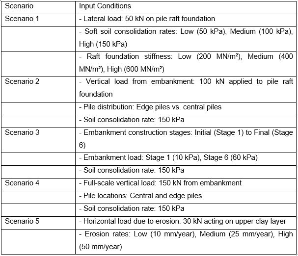
Table 1 Input Conditions for Each Scenario
Scenario 1: Horizontal Displacement in Pile Raft Foundation
The first analysis looks at the horizontal displacement of the pile raft foundation system for the loads acting laterally on this system. The analysis based on the RS2 indicates that horizontal movements are much significant in the relatively soft soil with higher consolidation rate. Pile movements in these areas are large under lateral loads; therefore, the distribution of loads on the raft foundation minimizes the detrimental impacts. Notwithstanding, the effectiveness study shows that increasing the stiffness of the raft foundation leads to the reduction of the overall horizontal displacement thus enhancing the stability of the bridge abutment.
Key findings:
• High soil consolidation rates lead to greater lateral displacements.
• Raft foundation stiffness plays a crucial role in mitigating horizontal displacement.
Scenario 2: Vertical Displacement in Pile Raft Foundation
In this case, the vertical displacements are considered. From analytical results of RS2 software it identified that the vertical displacement is smaller than the horizontal displacements but notable especially when soil conditions are soft. The piles undergo a downward displacement through the load of the embankment and the structural load which passes through the raft foundation to the piles. Intensity of the vertical settlement is higher at the edges of the foundation where piles are installed and the soil does not have adjacent counterpart to support it.
Key findings:
• Vertical displacements are concentrated near the edges of the foundation.
• Increasing the foundation stiffness reduces vertical movement.
Scenario 3: Embankment Initial Stage vs. Embankment Stage 6
This scenario aims at analyzing the evolution process of the embankment. During this stage, the displacement of both piles and soil is quite checked in the sense that major movements have hardly occurred. Moreover, in stage 6 of the embankment construction, both the soil structure and pile displacement are highly affected and altered. The bottom figure depicts the sum impact of the loading – horizontal and vertical deformations rise with each height added to the embankment. This scenario applies the concept of time dependent soil consolidation and the stability of the embankment.
Key findings:
• The initial stage shows minimal displacement.
• Stage 6 reveals substantial horizontal and vertical displacement due to cumulative loading.
Scenario 4: Vertical Settlements
Figure 5 below indicates that settlement is not evenly distributed with the central part of the foundation recording lesser settlement than the outer parts. This is due to the fact that the central area is able to handle more loads owing to the high density of piles. In the process of consolidating the soil it is discovered that the degree of subsequent settlement gradually increases, but does not exceed the admissible in terms of structure. From this, the simulation underscores the significance of controlling the kind of settlement that impacts on the differential movement that enhances the break up of the connecting medium, in this case the abutment of the bridge.
Key findings:
• Central areas of the foundation experience less vertical settlement.
• Differential settlement needs to be minimized to maintain structural integrity.
Scenario 5: Horizontal Movements in the Clay Layer (Soil Erosion)
The last case considered is the influence of soil erosion as a factor affecting horizontal motions in the clay layer. The RS2 analysis shows that with increase in erosion of the soil, the piles horizontal stiffness decreases, particularly in the upper clay layer. These lateral movements are especially more expressed in regions, where the processes of soil erosion are most acute. The results discussed above will stress the need to practice overhead erosion control measures such that excessive lateral movement cannot happen and hence cause a structural failure of the piles and abutment.
Key findings:
• Soil erosion significantly affects lateral stability, increasing horizontal movements.
• Erosion control measures are crucial to ensure long-term stability of the pile foundation system.
.png)
.png)
Table 2 Numerical Results for Each Scenario
3. Summary of Findings from the Results
The findings of this present study from the RS2 simulations are also in consonance with the research objectives formulated at the beginning of this paper and from previous or similar findings such as the one done by M.K. Kelesoglu.
• Simulation results of RS2 was well compared to the empirical data.
• Comparison of real lateral piles deflection with the analysis results indicates that soil consolidation highly influences it.
• The superstructure of pile raft foundations diminished lateral movement in soft ground.
• Lateral stability of piles is significantly influenced by the phenomenon of soil erosion.
References
![]()
Reports
MME501 Materials of Engineers Report 3 Sample
Task 1:
Case Study on Materials Used in Modern Aircraft:
Carefully read the below text and answer the following questions.
It is strongly suggested to refer to the lecture notes, recommended textbooks, and other literature in formulating your answers. It is not necessary to use question numbers, but make sure to provide sufficient explanations to cover the questions.
You may use figures, diagrams and tables to illustrate your answer and provide citations and references, where necessary.
The answer should contain a minimum of 500 words.
“Composite materials have been called the shape of aerospace’s future. With their winning combination of high strength, low weight and durability, it’s easy to see why. For more than 30 years, Airbus has pioneered the use of such materials in its commercial jetliners, from the cornerstone A310’s vertical stabiliser to today’s A350 XWB – on which more than half of the aircraft’s structure is composite.
In essence, a composite material is made from two or more constituent materials with different physical or chemical properties. When combined, the composite material exhibits beneficial physical characteristics quite different from what the individual components alone can provide. Commonly- recognised composites in everyday life include plywood and reinforced concrete.
From nose to tail, Airbus utilizes advanced composites in its jetliner product line that have been at the forefront of materials science. One particular standout material is carbon-fibre reinforced plastic, or CFRP. Composed of carbon fibres locked into place with a plastic resin, CFRP offers a better strength-to-weight ratio than metals and has less sensitivity to fatigue and corrosion. In short, it’s lighter than aluminium, stronger than iron, and more corrosion-resistant than both.
Like all composites, the strength of CFRP results from the interplay between its component materials. By themselves, neither the carbon fibres nor the resin is sufficient to create a product with the desired characteristics to be integrated on an aircraft. But once combined in multiple, integrated layers and bonded, the CFRP airframe component or aerostructure takes on the strength and load- bearing properties that make it ideal for aviation use.”
(Source: https://www.airbus.com)
Discuss advantages of using non-metals in aircraft structures.
Investigate the extent of usage of non-metals in A350 aircraft or a similar aircraft.
Compare the use of CFRP in A350 aircraft with traditional materials used for older versions of aircraft. It is required to compare strength, durability and other key properties and quote suitable examples of components for which these different materials are used.
Investigate the limitations of using non-metals in aircraft structures.
Task 2:
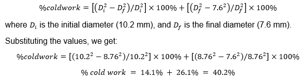
“Strain hardening is the phenomenon whereby a ductile metal becomes harder and stronger as it is plastically deformed. Sometimes it is also called work hardening, or, because the temperature at which deformation takes place is “cold” relative to the absolute melting temperature of the metal, cold working. Most metals strain harden at room temperature” – Materials Science and Engineering, Callister, 8th Edition
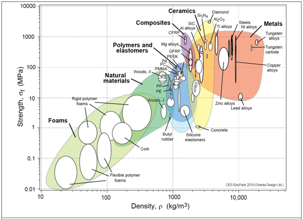
The figure on the left below demonstrates how steel, brass, and copper increase tensile strength with increasing the degree of cold work. The price for this enhancement of strength is in the ductility of the metal. The reduction in ductility with the percentage of cold work is shown in the figure on the right.
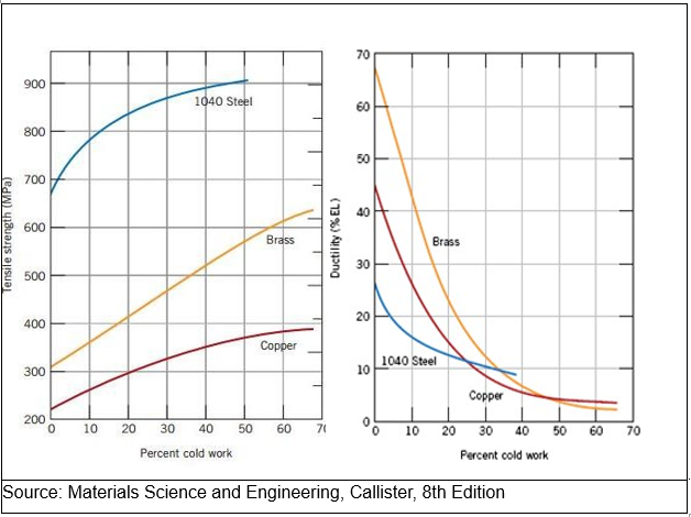
Source: Materials Science and Engineering, Callister, 8th Edition
Once a cold worked material is heat treated, the recrystallization process resets the cold work properties to zero cold work case. Therefore, when excessive cold work is required without sacrificing the ductility of a material, a component is partially cold worked which is followed by heat treatment to reset the properties before the next stage of cold work. This process may be repeated for number of times as required.
Use the above explanation and the graphs to answer the following questions.
A cylindrical rod of brass originally 10.2 mm in diameter is to be cold worked by drawing. The circular cross section will be maintained during deformation. A cold-worked tensile strength in excess of 380 MPa and a ductility of at least 15 %EL are desired. Furthermore, the final diameter must be 7.6 mm.
Hint: The following process may be followed to achieve the requirement.
Calculate the percentage cold work expected during the drawing which reduces the diameter from 10.2 mm to 7.6 mm. Use the given diagrams to justify that the required tensile strength and/or the ductility cannot be matched with the proposed amount of cold work.
As an alternative, consider the required values of tensile strength and the ductility, separately to determine the target values of percentage of cold work and hence propose a suitable range for the percentage of cold work. Considering the range, decide on a suitable amount of cold work.
It is suggested that to reduce the diameter of the rod to an intermediate value to satisfy the proposed percentage of cold work in b) above. Apply the cold work formula to determine the final diameter of the rod after this first stage of the cold work.
Explain the rest of the process of reducing the cross section to 7.6 mm diameter whilst achieving the required ductility and tensile strength. What is the percentage of cold work retained in the rod?
Task 3: (30 marks)
3.1
It is required to select suitable material/s for an engineering application that satisfies the following requirements:
Tensile strength more than 700 MPa
Modulus of elasticity more than 100 GPa
Density less than 3000 kg/m3
3.2
Answer following questions.
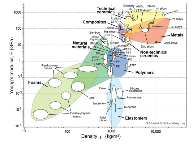
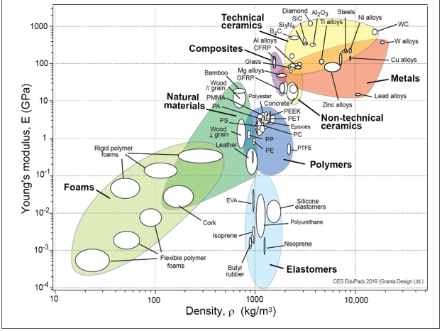
Use the first two Ashby charts (below) to select a set of materials that satisfy these requirements.
Use the third Ashby chart, standard textbooks and/or any other resource/s to refine your selection to present three best materials if the following additional requirements are also to be fulfilled.
Corrosion resistance
Low cost
Sustainability
Explain the selection process in each case quoting any references used.
.png)
Solution
Task 1 (a)
In contrast to conventional metals, the use of non-metallic materials, particularly composites, offers a number of benefits. Here are a few of the main advantages:
1. Excellent strength to weight ratio: Composites outperform conventional metals in this regard. For instance, aluminium is substantially heavier than carbon fibre reinforced plastic (CFRP), a prominent composite material used in aerospace applications, but it has comparable or even higher strength.
2. Durability: In difficult situations, composites are also more durable than conventional metals. They are perfect for aviation constructions that must withstand harsh circumstances since they are less sensitive to fatigue and corrosion.
3. Design Adaptability: Composites may be shaped into intricate forms, increasing design adaptability and maximising material usage. Reduced weight and improved fuel economy are the outcomes, which are crucial for commercial aircraft.
4. Lower Maintenance Costs: Due to their longevity, composites need less maintenance than conventional metals. Over the course of an aircraft, this can save a lot of money.
5. Better Performance: Using composite materials in aircraft constructions can lead to better performance, especially in terms of speed, range, and cargo capacity. This is due to the fact that composites have a greater strength-to-weight ratio, which leads to improved efficiency and performance.
Task 1 (b)
Modern commercial aircraft like the Airbus A350 XWB (Extra Wide Body) heavily rely on non-metallic components, notably composites. In reality, composite materials, including carbon-fibre reinforced plastic (CFRP) and other cutting-edge materials, make up more than half of the aircraft's construction. Here are some instances of how the A350 uses composite materials:
1. The A350's wings are predominantly constructed of CFRP, which is stronger and lighter than aluminium. By stacking pre-impregnated carbon fibre material in a mould and then curing it at high temperatures to form a solid, one-piece structure, a novel manufacturing technique is used to manufacture the wings.
2. Fuselage: Materials like as CFRP and other composites are used to construct the A350's fuselage. Similar stacking and curing techniques are used to create the fuselage to generate a sturdy, light-weight structure that is corrosion- and fatigue-resistant.
3. The A350's horizontal tail plane and vertical stabiliser are likewise composed of composite materials, including CFRP. To build a sturdy, lightweight framework, these components are made utilising a combination of manual lay-up and automated lay-up procedures.
4. Landing Gear Doors: GLARE (Glass Laminate Aluminium Reinforced Epoxy), a composite material, is used to construct the landing gear doors of the A350. The hybrid material GLARE is made of layers of fibreglass and aluminium, creating a robust, light-weight framework that is resistant to fatigue and corrosion.
Task 1 (c)
The A350 aircraft's usage of CFRP marks a substantial change from the conventional materials used in earlier models of aircraft. Some of the main variations between the two are as follows:
Strength: Compared to conventional materials like aluminium or steel, CFRP offers a better strength-to-weight ratio. For instance, the wing of the A350 XWB is entirely composed of CFRP, which results in a weight savings of 25% when compared to a traditional metal wing of comparable size. Lower running costs and improved fuel economy are the consequences.
Durability: Compared to conventional metals, CFRP is less prone to corrosion and fatigue. For instance, the 53% CFRP fuselage of the A350 XWB makes it more corrosive resistant and less prone to fatigue fractures. Longer service life and lower maintenance expenses result from this.
Component examples: In addition to the wing and fuselage, the A350 XWB also heavily utilises CFRP in the tail section, nose cone, and doors.
Task 1 (d)
There are several advantages for The Assignment help to using non-metals, notably composites, in aeroplane construction, as the text emphasises. There are several restrictions to take into account, though:
1. Price: Producing composite materials may be expensive and necessitates specialised production techniques. The materials themselves may be more expensive than conventional metals, and the initial investment in production-related tools and training may be high.
2. Maintenance: Compared to typical metal constructions, composite structures may require more effort and time to fix. It may be necessary to purchase specialised tools and training, which will raise the overall cost of maintenance.
3. Robustness: Despite being more resilient than metals in general, composites might be more vulnerable to damage from external elements including UV light, dampness, and severe temperatures.
4. Fire resistance: Composite materials can be less fire-resistant than metals, and may require additional fireproofing measures to meet safety regulations.
Top of Form
Task 2 (a)
To calculate the percentage cold work, we can use the formula:
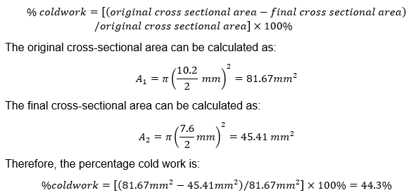
According to the figure on the left, brass's tensile strength improves as the amount of cold work increases; a cold-worked tensile strength of more than 380 MPa may be attained with a cold work of around 50%. The figure to the right shows, however, that brass's ductility rapidly declines as the amount of cold work increases, and a ductility of at least 15%EL cannot be obtained with a cold work of 50%. Because of this, the suggested level of cold work (44.3%) is insufficient to provide the appropriate levels of tensile strength and ductility.
Task 2 (b)
Looking at the figure on the left, we can see that a cold work of roughly 50% is necessary for brass in order to attain the appropriate tensile strength of 380 MPa. But as we can see from the figure on the right, a 50% cold work yields a ductility of less than 10%EL. Looking at the figure to the right, we can see that a cold work of less than 30% is necessary for brass in order to reach the needed ductility of at least 15%EL. But as we can see from the figure on the left, a 30% cold work yields a tensile strength of about 280 MPa, which is significantly less than the desired 380 MPa.
To attain the appropriate tensile strength and ductility, we must thus choose an acceptable range of cold work. The data show that a tensile strength of around 400 MPa and a ductility of about 12%EL may be obtained from a cold work of about 40%. In light of this, 35–45% of cold labour would be appropriate in this situation. We may select a 40% cold work, which is towards the middle of the range and should produce tensile strength of about 400 MPa and ductility of about 12%EL.
Top of Form
Task 2 (c)
To achieve a cold work of 40%, it is suggested to perform the cold work in multiple stages. Let's assume that the initial diameter of the rod is reduced to an intermediate value (D_i) such that the final diameter after the second stage of cold work is 7.6 mm.
From the formula for percentage cold work, we can write:
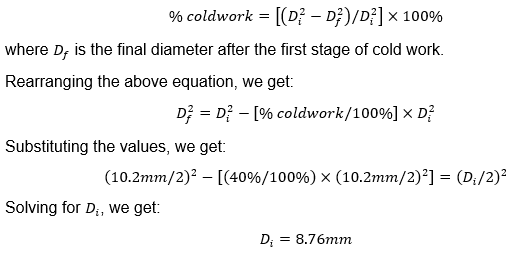
Therefore, the diameter of the rod should be reduced to 8.76 mm in the first stage of cold work, and then further reduced to 7.6 mm in the second stage of cold work to achieve a total cold work of 40%.
Task 2 (d)
To achieve a final diameter of 7.6 mm with a total cold work of 40%, the rod needs to be cold worked in two stages:
First stage: Reduce the diameter from 10.2 mm to 8.76 mm. This corresponds to a cold work of 14.1%.
Second stage: Reduce the diameter from 8.76 mm to 7.6 mm. This corresponds to a cold work of 26.1%.
After the first stage of cold work, the material should be heat treated to reset the cold work properties before the second stage of cold work. This is important to avoid excessive hardening and embrittlement of the material.
Assuming that the heat treatment successfully reset the cold work properties after the first stage, the total percentage of cold work in the final product will be:
Therefore, the percentage of cold work retained in the rod after the second stage of cold work is 40.2%. Since this value is close to the target range of 35-45% calculated in part (b), we can expect the final product to have a tensile strength of about 400 MPa and a ductility of about 12%EL, as discussed earlier.
Task 3
It is required to select suitable material/s for an engineering application that satisfies the following requirements:
Tensile strength more than 700 MPa
Modulus of elasticity more than 100 GPa
Density less than 3000 kg/m3
Task 3 (a)
To satisfy the given requirements, we need to find materials with a high tensile strength and modulus of elasticity, while also having a low density. We can start by looking at materials with high tensile strength and modulus of elasticity from the first Ashby chart.
Materials such as titanium alloys, high-strength steels, and some aluminum alloys have high tensile strength and modulus of elasticity. However, these materials are generally dense and may not meet the density requirement.
To meet the density requirement, we need to look at materials with a low density from the second Ashby chart, such as carbon fiber composites or polymer-based materials. However, these materials typically have a lower tensile strength and modulus of elasticity compared to metals.
Therefore, we need to strike a balance between these requirements by selecting a material that offers a good compromise between strength, stiffness, and density. One such material that meets these requirements is carbon fiber reinforced polymer (CFRP). CFRP has a tensile strength of around 700-1400 MPa, a modulus of elasticity of 100-300 GPa, and a density of around 1600-1900 kg/m^3. Other composite materials such as fiberglass or Kevlar may also be suitable depending on the specific requirements of the engineering application.
Task 3 (b)
To refine our selection of materials, we will consider the additional requirements of corrosion resistance, low cost, and sustainability. We will use the Ashby chart on strength versus relative cost per unit volume, along with standard textbooks and other resources, to select the three best materials.
Corrosion Resistance: For many engineering applications, especially those that involve exposure to hostile conditions like marine or aircraft settings, corrosion resistance is a crucial requirement. We will use the Ashby corrosion resistance vs strength table to choose materials that satisfy this criteria. Materials with strong corrosion resistance, high tensile strength, and elastic modulus include titanium, aluminium alloys, and stainless steel. However, they might not be affordable enough.
However, despite being less expensive, materials like polymers and composites might not provide the necessary level of corrosion resistance.
A fiber-reinforced polymer composite that employs an epoxy matrix and carbon or glass fibres is one substance that satisfies all three criteria. This substance offers excellent corrosion resistance, great strength and stiffness, and low density. In comparison to materials like titanium and stainless steel, it is also very inexpensive.
Low Cost: For numerous engineering uses, especially those requiring mass production or large-scale building, low cost is a crucial need. We will use the Ashby table on relative cost per unit volume vs strength to choose materials that satisfy this criterion.
Although materials like polymers and composites are typically less expensive than metals, they might not provide the necessary level of strength and stiffness. Although more expensive, metals like steel and aluminium alloys have higher strength and stiffness.
One substance that satisfies all three demands is aluminium 7075 alloy. This alloy has a comparatively low density of near 2800 kg/m3, a high tensile strength of about 600 MPa, and an elastic modulus of about 70 GPa. Moreover, it is relatively low in cost compared to other high-strength metals such as titanium.
Sustainability: As businesses and organisations work to lessen their environmental effect, sustainability is becoming a criterion for engineering applications that must be met. We shall take into account aspects including recyclability, energy usage during manufacture, and the environmental effect of the material's life cycle when choosing materials to satisfy this criterion. Materials like metals and alloys take a lot of energy to manufacture, and this process frequently pollutes the environment. On the other hand, recyclable materials with a lesser environmental effect include composites and polymers.
Composite made of bamboo fibres and reinforced with polymer is one material that satisfies all three criteria. Compared to other materials like metals and synthetic polymers, bamboo is a more environmentally friendly resource since it is very sustainable and regenerative. A range of technical applications can benefit from the strength and rigidity of bamboo fiber-reinforced polymer composites.
Finally, we have chosen three materials that satisfy the initial specifications of high tensile strength, elastic modulus, and low density. We then used Ashby tables and other resources to narrow down our pick based on the additional criteria of corrosion resistance, affordability, and sustainability. A fiber-reinforced polymer composite, aluminium 7075 alloy, and a composite made of bamboo fibres were chosen as the materials. These materials are useful for a variety of technical applications because they provide a reasonable balance between strength, stiffness, and other criteria.
Reference
.png)
Assignment
Technology and Engineering Management Assignment Sample
Question 1
Sandeep, Sally and Srineth are recent graduates from UC who have come together to launch an innovative start-up company, UCSmartHealth. Their vision is to support a wide variety of applications to meet different use cases such as general wellness monitoring, patient monitoring of chronic health conditions, connected hearing aids, assisted living for the elderly, sports analytics, as well as military applications (e.g. wearables that can detect post-traumatic stress disorders (PTSD), depression, etc). You know Sandeep, Sally and Srineth and they are very committed to their vision, however, the team does not have the experience to confidently take the first steps. They have reached out to you as a respected engineering management professional to help them define their strategic objectives and start to define their product development journey.
a. Using SMART goal setting principles, develop an artefact using the MOST framework (Mission Objectives, Strategies and Tactics) for UCSmartHealth that addresses the key activities they will need to undertake.
Question 2
Now that they have a MOST, they need to review the legal structure of their organisation. Sandeep and Sally have Sole Trader ABNs. They are unsure whether this is enough. They will need to employ staff, seek funding through loans or investment, and manage various risks as they develop their technology. They have again asked for your help.
Research the different forms of business registration for an Australian-based businesses.
a. With what you know about UCSmartHealth, what do you believe would be the best structure and why?
Include your assumptions about the business to help explain your advice to them. (Hint: A link in Canvas from week 1 is to an Australian Government website that will help you work through this question).
Question 3
Now that the business has been formed, the team is looking to build a team to develop their products. UCSmartHealth has asked you to provide advisory services to support the recruitment process. They have decided to take an agile approach to managing the development of their product, and they’ve asked you to keep this foremost in your mind when providing your advice. Their specific questions for you are:
What roles should we advertise and why?
Should we be looking for applicants with experience in agile projects and why?
Would you reference skill levels from the SFIA framework to assist applicants? Explain why or why not.
Once the team is recruited and has started at UCSmartHealth, what activities do you recommend we do to get the team focused on innovating and delivering.
Question 4
With the company now formed and staff positions filled, the team gets down to business and is racing against time to come up with its first batch of innovative products – smart wearables that can detect falls in elderly patients. Paco is a new engineer who is also in a team leader role. Paco has been trying to build an inclusive team by democratising the development of ideas within the team and encouraging team members to make contributions. Paco is worried that he is running out of time and fears the company might lose out on potential market share and fall behind its competitors if they do not seize the moment and roll out this new product as soon as possible. Paco is keen on carrying everyone along but several meetings later and with the product launch date around the corner, the team is still deliberating on some of the technical features of the product and this is putting the team under tremendous pressure. UCSmartHealth’s leadership team has reached out to you to help, as they are concerned the team is going to miss a key opportunity in the market, and fear the team is focused on arguing over their own technical preferences instead of acting in response to customer feedback.
Discuss the pros and cons of Paco’s approach to the team leader role.
Paco established a team charter when he took on the team leader role. What might be missing in the team charter?
What evidence is there to suggest the team has stopped listening to customer feedback? What questions might you ask the team to gain further insight?
You provide your findings to the UCSmartHealth team, and they ask you to work directly with Paco to turn things around. What advice will you provide to Paco?
Question 5
UCSmartHealth has successfully developed 2 flagship products – UCAware which provides situational awareness of the environment for assisted living among the elderly and UCPredict which incorporates artificial intelligence (AI) technology to help predict the probability of occurrence of PTSD among war veterans.
After 6 months of production, the company has been able to post the mid-year sales figures presented in the table below.
.png)
UCAware has high levels of customer engagement and perceived value, supported by strong sales figures. On the other hand, UCPredict has high levels of customer engagement, but perceived value is dwindling. Customers love UCPredict and want it to be successful, but features requested by customers have not been scoped or added to the product backlog.
You decide to interview users of UCPredict to gain specific insights on product improvements for your development team.
Design a set of questions that will draw out both the pain points and desirable solutions for customers that will enable you to build a Product Backlog
Question 6 (4 marks) 250 words
UCSmartHealth’s UCPredict development team is using a kanban board to track the flow of work as part of their adoption of the Scrum framework. They’ve asked you to review it given your experience and exposure to agile ways of working as an engineering professional.
.png)
What observations do you have?
What advice would you give to increase the flow of value?
Solution
Questions 1:
Mission: UCSmartHealth's mission is to become a leading provider of innovative and comprehensive smart health solutions that improve the quality of life for people around the world.
Objectives
Develop a portfolio of smart health products that meets the needs of various use cases, such as general wellness monitoring, patient monitoring of chronic health conditions, connected hearing aids, assisted living for the elderly, sports analytics, and military applications.
Establish strategic partnerships with healthcare providers, insurance companies, and technology companies to expand market reach and increase brand recognition.
Build a strong reputation for innovation and reliability in the smart health industry through continuous research and development.
Achieve a 15% market share within the next five years.
Strategies
Conduct market research to identify the needs of the target market and develop products that address those needs.
Establish partnerships with healthcare providers, insurance companies, and technology companies to increase access to the target market and build brand recognition.
Invest in research and development to continuously innovate and improve the product portfolio.
Leverage social media and other digital marketing channels to increase brand awareness and drive sales [1].
Tactics
Conduct surveys and focus groups to understand the needs of the target market and prioritize product development.
Attend healthcare and technology conferences to establish partnerships and increase brand visibility.
Hire a dedicated research and development team to drive innovation and product improvement.
Develop a comprehensive social media marketing plan and leverage influencers to increase brand awareness and drive sales.
Establish key performance indicators (KPIs) to track progress towards objectives and adjust strategies as needed.
Question 2
Based on the information provided, UCSmartHealth is a startup company that plans to develop and market a range of smart health solutions. The company plans to employ staff, seek funding through loans or investment, and manage various risks as they develop their technology.
Considering the potential growth and complexity of the business, I would recommend that UCSmartHealth consider registering as a proprietary limited company (Pty Ltd) in Australia. This legal structure provides the company with separate legal status and limits the liability of its shareholders. This means that the personal assets of the shareholders are protected in the event of any legal issues or debts that the company may incur.
Assumptions:
UCSmartHealth plans to expand and grow in the future.
The company plans to employ staff and seek funding through loans or investment, which requires a more formal business structure.
There may be potential legal risks associated with the development and marketing of smart health solutions, which can be mitigated through a Pty Ltd company structure [2].
In addition, registering as a Pty Ltd company can provide UCSmartHealth with greater credibility and access to investment opportunities. It also allows the company to issue shares to investors, which can help raise funds for business expansion. While the decision to register as a Pty Ltd company should be carefully considered and consulted with a legal professional, it appears to be the most suitable legal structure for UCSmartHealth given their business goals and assumptions.
Question 3
a)
Based on an Agile approach, I recommend that UCSmartHealth consider the following roles for their development team:
Product Owner: This role is responsible for defining and prioritizing the features of the product backlog, and ensuring that the development team is aligned with the business objectives of UCSmartHealth. Scrum Master: This role is responsible for ensuring that the development team adheres to Agile principles and processes, facilitating daily stand-ups, and removing any impediments that prevent the team from achieving their objectives.
Developers: These roles are responsible for the development of the product, including coding, testing, and deployment.
Quality Assurance (QA) Engineer: This role is responsible for ensuring that the product meets the quality standards and specifications defined by the Product Owner.
UX Designer: This role is responsible for designing the user interface and ensuring a positive user experience [3].
b) Yes, it would be beneficial for UCSmartHealth to look for applicants with experience in Agile projects. This is because Agile projects have unique methodologies, principles, and practices that require a different mindset and approach to project management than traditional project management. Experienced Agile practitioners have the necessary skills to collaborate effectively, respond to change, and deliver value in a dynamic and fast-paced environment. They will also have a good understanding of Agile frameworks such as Scrum or Kanban, which will help them contribute to the success of UCSmartHealth [4].
c) Yes, I recommend UCSmartHealth reference skill levels from the SFIA (Skills Framework for the Information Age) framework to assist applicants. The SFIA framework is widely used in the IT industry to provide a standard for skills and competencies required for specific job roles. By using this framework, UCSmartHealth can ensure that their job descriptions and requirements are aligned with industry standards, and that they attract the right candidates with the appropriate skills and competencies.
d) To get the team focused on innovating and delivering, UCSmartHealth can consider the following activities: Conduct Agile training and coaching sessions: This will help the team members understand the Agile principles and methodologies, and how they can apply them to their work. Set up a regular sprint cadence: This will create a sense of urgency and focus, and ensure that the team is delivering value regularly.
Foster a culture of collaboration and continuous improvement: Encourage the team to work together, share knowledge, and provide feedback to each other. Regular retrospectives can also help the team identify areas for improvement and adjust their processes accordingly. Empower the team: Trust the team to make decisions and solve problems on their own, and provide them with the resources and support they need to do their job effectively. Communicate effectively: Ensure that the team has a clear understanding of the product vision and goals, and that they are aligned with the business objectives of UCSmartHealth. Regular updates and feedback can help the team stay on track and motivated [4].
Top of Form
Question 4
a) Paco's approach of democratising the development of ideas and encouraging team members to make contributions is a good way to foster a culture of collaboration and inclusivity within the team. By doing this, he has also created an environment where team members can feel heard and valued, which can increase motivation and job satisfaction. However, the downside of this approach is that it can sometimes lead to analysis paralysis, where team members get bogged down in debates and fail to make decisions. This is particularly true when the team is under pressure to meet a deadline, as it can lead to missed opportunities and lost market share [5].
b) The team charter is an important document that outlines the goals, roles, and responsibilities of the team. However, there may be several aspects missing in the team charter that could help to prevent the current situation. These include:
Clear decision-making processes: The team charter should clearly outline how decisions are made, including who has the final say and what criteria are used to evaluate different options. This can help to prevent endless debates and ensure that decisions are made efficiently.
Timeframes and deadlines: The team charter for the assignment helpline should include clear timeframes and deadlines for different stages of the project, including when decisions need to be made and when deliverables are due. This can help to keep the team on track and prevent delays.
Customer feedback mechanisms: The team charter should outline how customer feedback is collected, analysed, and incorporated into the product development process. This can help to ensure that the team is responsive to customer needs and that the product meets market demands.
c) The fact that the team is still deliberating on technical features of the product close to the launch date is a clear indication that they may have lost sight of the customer feedback. To gain further insight, some questions that could be asked include:
How is customer feedback collected and analysed?
How often is customer feedback discussed in team meetings?
What changes have been made to the product based on customer feedback?
How are customer needs and preferences incorporated into the decision-making process?
What is the team's understanding of the target customer and their pain points?
How does the team prioritise features and functionality based on customer needs and feedback?
d) To turn things around, Paco should consider the following:
Prioritising the features and functionality of the product based on customer feedback and market demand. Setting clear deadlines and timeframes for decision-making and product delivery. Establishing a clear decision-making process that includes the identification of key stakeholders and the criteria used to evaluate options. Encouraging team members to provide constructive feedback, while also ensuring that debates do not derail the process. Ensuring that the team is aligned around a common goal and has a shared understanding of the target customer and their needs [8].
Questions 5
Here are some questions that can help draw out pain points and desirable solutions for customers of UCPredict:
How has UCPredict helped you so far? What specific features have you found most useful?
Are there any features missing from UCPredict that would make it more useful to you? If so, what are they?
Have you experienced any challenges or difficulties while using UCPredict? If so, can you describe them?
Have you tried any other similar products? If so, what do you think sets UCPredict apart from those products?
How frequently do you use UCPredict, and for what purpose(s)?
Are there any particular situations or scenarios where UCPredict has been particularly helpful to you?
How do you think UCPredict could be improved to better meet your needs or expectations?
Can you provide any specific examples of how UCPredict could be improved? What features or functionality would you like to see added?
Is there anything about UCPredict that you find confusing or difficult to use? If so, what is it?
Is there anything else you would like to share about your experience using UCPredict?
Question 6
a)
Observations:
The kanban board seems to have too many columns, which can make it difficult to track the flow of work and increase lead time. The work items in the "To Do" column are not prioritized, which can lead to delays in starting work on high-priority items. The "Testing" column appears to be empty, which suggests that testing may not be given enough priority or may not be done consistently. There are no explicit policies for each column, which can lead to confusion and inconsistency in how work is done [6].
b)
Advice to increase the flow of value:
Simplify the kanban board by reducing the number of columns to a minimum that represents the core workflow. Prioritize work items in the "To Do" column based on their importance and urgency. Ensure that testing is given enough priority and done consistently by adding an explicit "Testing" column and defining policies for it. Establish clear policies for each column, including the definition of "Done," to ensure consistency in how work is done and increase transparency. Consider implementing a pull system to prevent overloading team members with too much work and to improve flow [7].
References
.png)
Reports
ENEM28001 FEA for Engineering Design Report 2 Sample
Task Description:
The goal of this assessment is to test your ability to use ANSYS Workbench®.
You will develop a portfolio of 5 workshops as indicated below. Marks as indicated.
Workshop 1: 2D Analysis of Rack and Pinion System
Carry out a full analysis of the workshop, including the extension tasks on the last slide. In addition, insert a contact tool and examine the nature of contact between the rack and the pinion.
Workshop 2: Meshing
Carry out the meshing workshop using the various meshing methods in ANSYS Workbench.
Workshop 3: Transient Thermal Analysis
Carry out the workshop on phase change heat transfer analysis.
Workshop 4: Stresses due to Shrink fit between 2 cylinders
A hollow cylinder is shrink fitted in another. Both cylinders have a length, ‘l’. The flat surfaces of both cylinders are constrained in the axial direction while free to move in the radial and tangential directions. An internal pressure, P is applied on the inner surface of the inner cylinder. Assume all dimensions and pressures.
1. Set up an FE model and examine the maximum tangential stresses in both cylinders.
2. Verify and validate your results using thick cylinder theory.
Hints: (i) Tangential stresses can be obtained by using the cylindrical coordinate system in ANSYS Workbench, (ii) To simulate interference, consider contact type as ‘rough’ with interface treatment set to ‘add off set’ with offset = 0.
Workshop 5: Fatigue Analysis
Submit the workshop on strain-based variable amplitude, proportional load fatigue analysis.
Solution
Workshop 1
1. Introduction
A Rack and Pinion system's performance, safety, and efficiency may be assessed using critical engineering analysis. This research used ANSYS Workbench to analyze a Rack and Pinion system in 2D. Deformation, stress, strain, and rack pinion contact behavior are examined in this investigation. To model real world operating settings, the research uses frictionless support, distant displacement, and other boundary conditions. Rack and pinion systems are used in steering mechanisms in cars and linear motion systems in industrial machines. Understanding their behavior in diverse situations is crucial for design optimization and dependability. For Assignment Help, The Rack and Pinion system's pitch, dimensions, and tooth profiles are correctly modeled to start the study. To replicate the system's operating environment, boundary conditions reflecting physical restrictions and external pressures are introduced. This assesses stress distribution, deformation patterns, and contact behavior to ensure system safety and performance.
This report also examines the project requirements' extension tasks, which investigate advanced system behavior. The rack-pinion interaction may be examined in ANSYS Workbench using a contact tool to reveal frictional forces and contact stresses. This research helps engineers and designers improve the Rack and Pinion system by revealing its behavior. This extensive study's methodology, analytical findings, and conclusions will be explained in the following parts.
2. Problem Description
The goal is to analyze and evaluate a Rack and Pinion system, a common mechanical arrangement in engineering. Understanding the system's deformation, stress distribution, and contact characteristics under varied operating situations is the main goal. ANSYS Workbench is used to model and analyze the system.
A linear rack and rotary pinion gear make up a Rack and Pinion system. Rack, a straight toothed bar, is the linear element, while pinion gear, a circular gear, is the rotary element (ROY, 2021). The mechanism works simply: the pinion gear connects with the rack to turn rotary motion into linear motion or vice versa. Many technical applications use this method. It's used in automobile steering systems to convert the steering wheel's rotating motion into linear motion to operate the front wheels. Industrial automation equipment like CNC (Computer Numerical Control) machines employ Rack and Pinion systems for precise linear positioning.
In such applications, system efficiency and dependability are crucial. Thus, this research analyses its performance under various loads and situations, including deformation, stress, strain, and contact behavior (Bernabei et al. 2022). This study helps engineers and designers optimize the system for performance and durability in various engineering applications.
3. Assumptions for Analysis
In this study, to simplify and simulate the Rack and Pinion system model in ANSYS, various assumptions were made. To model and understand findings efficiently while recognizing real-world system complexity, several assumptions are necessary.
- The study assumes linear elastic behavior for all materials in the Rack and Pinion system. This keeps Young's modulus and Poisson's ratio constant under applied loads. Material nonlinearities like plastic deformation are not studied.
- The study assumes equilibrium and continuous loads. The static analysis ignores dynamic influences like vibrations and transient reactions (Babu et al. 2021).
- They simplified the geometry of the Rack and Pinion components. It assumes flawlessly machined components without tooth profile or surface roughness deviations. Real-world geometry deviations are ignored.
- The study assumes frictionless rack pinion contact. Friction affects system behavior, yet include it complicates analysis. The following analysis may include friction for a more complete picture.
- Assumed isotropic materials have consistent qualities in all directions. This assumption simplifies analysis but may not accurately reflect anisotropic materials.
- Contact analysis assumes linear contact behavior, where contact forces between rack and pinion teeth fluctuate linearly with deformation. We ignore nonlinear contact behavior such as significant deformations or plasticity.
4. Analysis Methods
Performing the analysis, there has been a focus on various functions in the Ansys workbench to understand and analyze the rack and pinion system. The applied methods are described below.
4.1 Geometry and contact tool
.png)
Figure 1.1: Geometry of the Rack and Pinion system
(Source: ANSYS)
Figure 1 shows Rack and Pinion 2D geometry. A linear rack, straight-toothed bar, and pinion gear, circular-toothed gear, are shown. (Vu et al. 2022) Rotary motion becomes linear or vice versa when the pinion contacts the rack. This mechanical arrangement is used in many technical applications.
.png)
Figure 1.2: No separation contact tool
(Source: ANSYS)
Figure 2 shows ANSYS's specialized contact tool for examining rack-pinion contact behavior. This contact tool analyses their interaction, including frictional effects and contact forces, without separating them. This tool improves simulation accuracy, allowing engineers to understand Rack and Pinion system contact mechanics.
4.2 material Assignment and Mesh generation
.png)
Figure 1.3: Material Assignment
(Source: ANSYS)
Performing the analysis structural steel has been assigned as the material of the rack and pinion system.
.png)
Figure 1.4: Mesh generation
(Source: ANSYS)
Figure 4 shows the crucial ANSYS mesh-generating stage. The model is discretized using 1.5 mm elements for accuracy. The computational domain has 5,842 nodes and 1,829 elements from this thorough meshing. Mesh creation is crucial to simulation accuracy and dependability. The mesh's tiny granularity lets engineers examine stress, strain, and deformation patterns to understand the Rack and Pinion system's structural behavior under different situations.
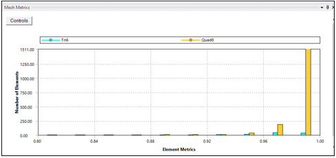
Figure 1.5: Mesh Element Quality Matrices
(Source: ANSYS)
In Figure 5, mesh element quality matrices range from 0.92 to 1, indicating excellent quality. These quality matrices show ANSYS analysis mesh element uniformity and appropriateness. Values near 1 indicate high-quality components, whereas 1 indicates full geometric congruence. This consistency guarantees the mesh correctly depicts geometry and minimizes simulation distortions. Such high-quality parts ensure the analysis's accuracy and dependability, improving the comprehension of the Rack and Pinion system's structural behavior.
4.3 Boundary Conditions
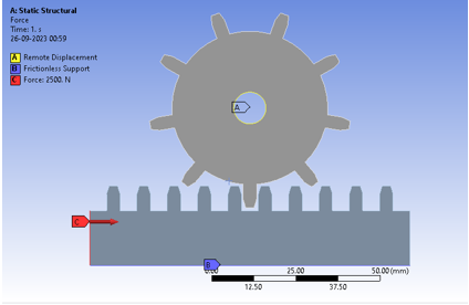
Figure 1.6: Boundary Conditions
(Source: ANSYS)
ANSYS boundary conditions are essential for modeling car rack and pinion steering systems. At point A, a Remote Displacement boundary condition allows the pinion to travel horizontally 30 mm in 1 second. This properly simulates steering wheel rotation, and starting rack action. Point B uses a Frictionless Support to secure the rack to the chassis by limiting all degrees of freedom. This keeps the rack immobile throughout the simulation, imitating its real-world use. These boundary conditions allow the study to derive performance characteristics like the reaction force at the pinion, which affects steering effort. Stress and deformation values of rack and pinion components are also assessed to determine system structural integrity.
4.4 Solver Settings
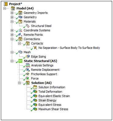
Figure 1.7: Solver Settings
(Source: ANSYS)
The above figure shows the solver setting for the analysis.
5. Results
The Rack and Pinion system's complete ANSYS study reveals its mechanical behavior under different situations. Under properly constructed boundary conditions, this approach explains the system's deformation, stress distribution, and contact mechanics. Similar to a vehicle's steering system, boundary conditions imitate real world events, making these discoveries important to engineering (Khalifa, 2023). These discoveries improve Rack and Pinion system design, efficiency, and safety, advancing mechanical engineering practices and assuring dependable performance in varied engineering settings.
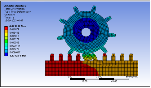
Figure 1.8: Total Deformation
(Source: ANSYS)
Total Deformation analysis, based on boundary conditions, provides valuable insights into Rack and Pinion system structural behavior. The system's minimal deformation value of 1.24E 05 indicates structural integrity under operating loads. Even while 2.37E 02 is high, it's within acceptable limits, showing the system's stress tolerance. The boundary conditions simulate real world circumstances well since the average deformation of 1.20E-02 shows a balanced reaction to applied forces. These findings confirm the system's stability and give crucial data for design and safety improvements.
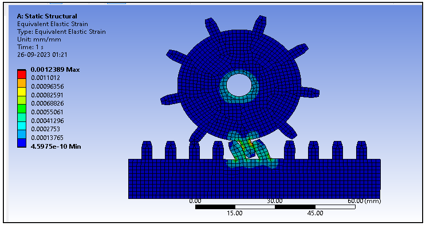
Figure 1.9: Elastic Strain Distribution
(Source: ANSYS)
Elastic Strain Distribution study inside the boundary conditions exposes Rack and Pinion system deformation properties. Under these circumstances, the minimum elastic strain is 4.5975e 010, indicating structural stability. The maximal score of 1.2389e 003, albeit higher, is within an acceptable range, suggesting moderate stress tolerance. At 5.7506e 005, the average elastic strain balances applied forces, proving that boundary conditions simulate real-world events. These insights aid system dependability and design optimization.
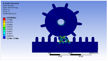
Figure 1.10: Strain Energy
(Source: ANSYS)
Strain Energy measured in mJ (millijoules) provides valuable insights into the Rack and Pinion system's mechanical behavior under defined circumstances. Little energy contribution of 5.54E-13 mJ suggests little system deformation or strain. However, the highest value of 0.8708 mJ, although larger, is within an acceptable range, reflecting the system's energy absorption and release. The system's energy distribution is balanced by the average Strain Energy of 29.585 mJ. These findings verify the system's structural integrity, aiding design and performance evaluation.
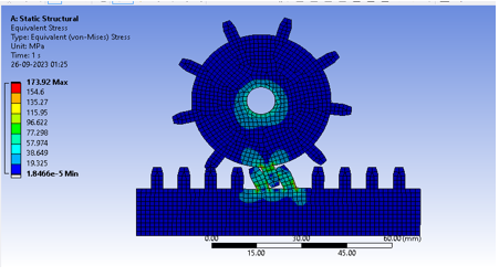
Figure 1.11: Equivalent Stress
(Source: ANSYS)
Equivalent Stress, measured in MPa (mega pascals), gives essential insights into the Rack and Pinion system's mechanical behavior under boundary circumstances. Minimum stress of 1.85E-05 MPa indicates exceptionally low stress levels, indicating a safe and stable system. While greater, the maximum stress measurement of 173.92 MPa is below critical failure criteria, proving the system can handle heavy loads. The average stress level, 10.677 MPa, shows that the boundary conditions simulate real-world events by responding evenly to applied forces. These findings are crucial for system design optimization and safety evaluations.
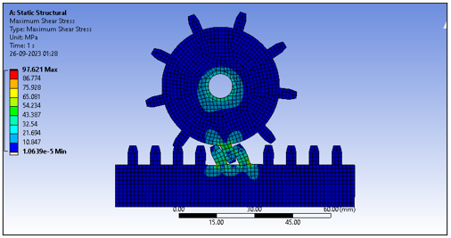
Figure 1.12: Maximum Shear Stress
(Source: ANSYS)
Maximum Shear Stress, measured in MPa (mega pascals), discloses important mechanical behavior of the Rack and Pinion system within the boundary conditions. Under these circumstances, the system's stability is shown by its minimum shear stress value of 1.0639e 005 MPa. At 97.621 MPa, the system's maximum shear stress is below critical limits, proving its durability. Due to the components' balanced shear stress of 5.8611 MPa, the boundary conditions accurately simulate real-world operating settings. These findings aid design and safety assessments.
6. Discussion
A thorough examination of the Rack and Pinion system using ANSYS software and boundary conditions revealed its mechanical behavior. These discoveries have major consequences for engineering design, performance optimization, and safety in different applications, especially rack and pinion steering systems in cars.
The system's deformation behavior is crucial to this investigation. System structural stability is shown by the minimal deformation of 1.24E 05. The system remains intact under boundary circumstances replicating the steering wheel's rotation, demonstrating its real world dependability. Though greater, the system's maximum deformation value of 2.37E 02 is within acceptable limits, demonstrating operational load capacity.
Evaluating the Elastic Strain Distribution strengthens the system. The minimal elastic strain of 4.5975e-010 shows that the system can withstand forces and preserve its form. The system can handle modest strain without deforming since the maximum value of 1.2389e-003 is tolerable.
Strain Energy analysis in millijoules emphasizes the system's energy intake and release. It shows modest deformation and strain with a minimum energy contribution of 5.54E-13 mJ. The highest value of 0.8708 mJ is substantially below critical limits, suggesting system robustness under load.
Equivalent and Maximum Shear Stress studies reveal the system's structural integrity. The minimal values of 1.85E 05 MPa and 1.0639e-005 MPa indicate that the system performs securely under difficult situations. Equivalent Stress is 173.92 MPa and Maximum Shear Stress is 97.621 MPa, significantly below failure criteria, demonstrating the system's capacity to bear heavy loads.
This research shows that the Rack and Pinion system is resilient and reliable under actual operating circumstances, as simulated by boundary conditions. These results influence design choices, allowing engineers to optimize system performance, safety, and effectiveness in varied engineering applications, notably automobile steering systems.
7. Conclusion
In conclusion, ANSYS Workbench software and carefully defined boundary conditions allowed for a thorough investigation of the Rack and Pinion system's mechanical behavior. These discoveries help improve the knowledge and performance of this basic mechanical arrangement utilized in many technical fields, including car steering systems.
Under boundary circumstances, the Rack and Pinion system shows low deformation, negligible elastic strain, and the capacity to absorb energy and carry the load. Maximum stress is substantially below critical limits, boosting system resilience.
These findings demonstrate the Rack and Pinion system's dependability and efficiency, making it suitable for demanding engineering applications. They also provide a solid platform for design refinement, optimization, and safety evaluations, advancing mechanical engineering practices and assuring Rack and Pinion system reliability in a variety of real world circumstances.
Workshop 4
1. Introduction
Structural analysis in engineering and materials science involves component interaction under mechanical limitations and pressure gradients. This study examines the difficult issue of shrink fit stresses between two cylindrical constructions using ANSYS Workbench software. This comprehensive research examines the complex relationship between geometrical limitations, internal pressure, and material characteristics of these cylinders, revealing important engineering design and structural integrity insights. The five components of this report's analysis are carefully selected to cover particular research aspects. The report starts with a thorough issue description and assumptions, laying the groundwork for later analysis. After discussing boundary conditions, loadings, solver settings, and meshing procedures in ANSYS Workbench, the computational framework is fully understood. ANSYS simulation data and analysis are the report's focus. It reveals the complicated stress distribution patterns in cylinders, providing critical insights into key areas, based on good theoretical concepts and thick cylinder theory. Post processing describes the methods and software used to extract and analyze crucial stress data. Therefore, this study synthesizes the investigation's findings and compares ANSYS results to theoretical predictions. The debate emphasizes the report's importance, making suggestions and highlighting its applicability to engineering applications. This thorough examination provides detailed knowledge of shrink-fit stresses between cylindrical structures, strengthening structural design approaches and setting the framework for additional research on this crucial topic.
2. Problem Description
Shrink fit between two cylinders is a major issue in mechanical engineering and structural analysis (Lee, and Hong, 2022). This study uses ANSYS Workbench software to analyze this phenomenon using finite element analysis (FEA). The issue involves two hollow cylinders with similar lengths, 'l,' concentrically positioned such that the inner cylinder is shrink-fitted into the outer one. In engineering, shrink fittings are used to link cylindrical components like shafts and bearings to transfer torque and axial loads.
This model's boundary conditions are crucial: both cylinders are restrained from axial movement, like a shrink fit, while preserving radial and tangential degrees of freedom. Inner cylinder pressure, 'P,' is applied. This analysis seeks to understand the stress distribution within these cylinders under internal pressure and identify the maximum tangential stresses, which are crucial to assessing assembly structural integrity (Feng et al. 2022). These results affect mechanical component design and performance evaluation and are essential for engineering system dependability and safety.
3. Assumptions for analysis
- A uniform temperature: This study ignores temperature changes and thermal impacts. The study assumes a constant assembly temperature.
- Geometry: The analysis assumes axisymmetric geometry, enabling a 2D axisymmetric model to reduce computer cost while retaining radial accuracy.
- The study assumes steady-state conditions, ignoring transient impacts like temperature variations or assembly.
- Assuming a perfect interference fit, this study does not account for material deformation or removal during shrink fitting (Ozbolt et al. 2022).
- Linear Pressure Distribution: The inner cylinder's inner surface has a linear pressure distribution depending on the internal pressure, P.
- Materials are expected to be constant and uniform across each cylinder's capacity.
- To simplify, the system is not loaded with external loads like axial or lateral loads.
4. Analysis Methods
A systematic approach was taken to analyze shrink fit stresses between two cylindrical structures using ANSYS Workbench, including model design, material assignment, mesh generation, boundary conditions, and result parameter definition (Wang et al. 2022). Methods used in the analysis are given here.
4.1. Modelling
First, ANSYS Workbench was used to create a 3D model of the two cylindrical components. Both cylinders' inner and outer radii and length (l), 100 mm, were exactly determined. The model appropriately depicts the shrink-fit assembly's geometry.
.png)
Figure 4.1: Geometry
(Source: ANSYS)
Figure 4.1 shows the ANSYS created shrink fit assembly geometry. The model's two cylindrical parts are precisely crafted to mimic engineering circumstances. The inner cylinder, with a 30 mm inner radius and 40 mm outside radius, is precisely crafted to imitate the assembly's fundamental component. Its proportions are carefully designed to mirror the innermost piece of the shrink fit arrangement, emphasizing its crucial role in assembly structural integrity. With an inner radius of 39 mm and an outside radius of 50 mm, the outer cylinder encloses the inner cylinder. This geometric shape perfectly mimics the shrink-fit assembly's outer component, emphasizing these two cylinders' interaction.
4.2. Material Assignment
Components were given material attributes to imitate cylinder mechanical behavior. The material was consistent for both cylinders. The material's elastic response to external forces was determined using Young's modulus (E) and Poisson's ratio (v).
.png)
Figure 4.2: Material Assignment
(Source: ANSYS)
Figure 4.2 shows the FEA model's material assignment. Steel, known for its strength and longevity, was chosen for the inner cylinder. Aluminum, which is lightweight and thermally conductive, was used for the outside cylinder. This planned material choice was designed to emulate a genuine engineering situation where various materials are routinely utilized in cylindrical assemblies, enabling stress interactions under internal pressure to be evaluated. Material assignments are crucial to accurately representing and analyzing the model's mechanical behavior.
4.3. Mesh creating
Meshing is crucial to FEM. A mesh was created for model correctness. For precise stress gradients, finer meshing was used in locations of importance like the cylinder contact interface (Cheng et al. 2022). Optimal element types and sizes were chosen to balance computing efficiency and accuracy.
.png)
Figure 4.3: Mesh
(Source: ANSYS)
The FEA model was rigorously meshed with 1 mm elements. This produced a polished mesh with many nodes and components. The mesh correctly represented complicated geometry and enabled exact stress and displacement calculations using 662,332 nodes and 146,046 components. To capture stress gradients, particularly in locations of importance like the contact interface between the two cylinders, the fine element size and extensive meshing were used. FEA findings are more accurate and robust with this small mesh resolution.
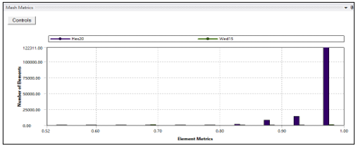
Figure 4.4: Mesh Element Matric Quality
(Source: ANSYS)
Figure shows the element quality distribution in the analyzed model's finite element mesh. The findings show element quality levels from 0.9 to 1.0. Element quality measures the mesh's geometric and structural integrity. A score of 1.0 indicates optimal, high quality parts, whereas values below 1.0 indicate deviations. The graphic shows the mesh's resilience and where element quality may differ from ideal. Finite element analysis requires excellent element quality, and this representation optimizes the mesh for accurate findings.
4.4. Boundary Conditions:
Creating shrink fit limitations and loadings, boundary conditions were created. The smooth surfaces of both cylinders were limited axially to simulate shrink fit assembly axial movement resistance. With radial and tangential degrees of freedom, the model simulated unconstrained movement in these directions.
.png)
Figure 4.5: Boundary Conditions
(Source: ANSYS)
In this ANSYS Workbench FEA, 500 MPa was supplied to the inner cylinder's inner surface to simulate internal pressure. This boundary condition simulates hydraulic or pneumatic stresses on cylindrical components. Fixed supports were placed on the flat surfaces of both cylinders to simulate shrink fit assembly limitations and prevent axial movement. The FEA model's structural analysis is based on these boundary conditions, which properly describe cylindrical constructions' key mechanical restrictions and loadings.
4.5 Solver Setting
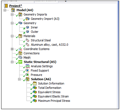
Figure 4.6: Solver setting
(Source: ANSYS)
The attached figure shows the applied solver setting for the analysis where it can be noticed that different tools and functions have been applied here to gen the analysis.
5. Results
In the findings section, the finite element analysis (FEA) results are thoroughly examined to understand shrink fit assembly behavior. Deformation, stress distributions, and critical tangential stresses are covered in this section. The cylindrical system's structural integrity and performance are illuminated by detailed examination of deformation patterns, stress concentration locations, and tangential stresses. These ANSYS Workbench findings provide a comprehensive view of the complicated interaction between geometry, material characteristics, and applied loads, helping engineers comprehend cylindrical assemblies
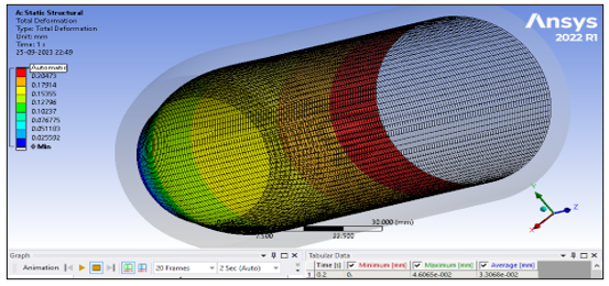
Figure 4.7: Total Deformation
(Source: ANSYS)
Total shrink fit assembly deformation is shown in the figure. The model had a maximum distortion of 0.23032 mm and an average of 0.16534 mm. These deformation values indicate the cylindrical components' movement under internal pressure. Deformation patterns are essential for measuring the assembly's mechanical reaction and design tolerances, as seen in the picture. This study helps ensure the structural integrity and functioning of such assemblages in engineering applications.
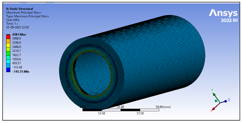
Figure 4.8: Tangential stress as maximum principle stress
(Source: ANSYS)
The tangential stress distribution in the shrink-fit assembly is shown in the figure. The greatest principle stress was 4583 MPa, with an average of 562.35 MPa. Tangential stress was lowest at 745.55 MPa. These data show complicated and varied assembly stress conditions. These insights help evaluate structural integrity and material failure by detecting crucial stress concentrations. This stress study provides a complete insight of the assembly's performance and significance to engineering design and safety.
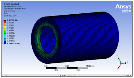
Figure 4.9: Elastic Strain
(Source: ANSYS)
The shrink-fit assembly's elastic strain is shown in the image. It shows elastic strain values from 6.6497e 020 to 1.7762e-002. The average elastic strain throughout the model was 3.0927e-003. These strain metrics reveal regions of minor and large elastic strain in the assemblage, revealing its deformation behavior. Understanding elastic strain distribution is crucial for understanding structural response and possible assembly deformations under load. This study optimizes the cylindrical system's design and ensures safety and performance.
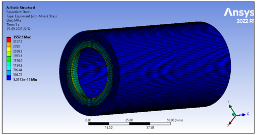
Figure 4.10: Equivalent Stress
(Source: ANSYS)
The graphic shows the shrink-fit assembly's comparable stress distribution. The model shows comparable stress values from 617.92 MPa to 3552.5 MPa. This approach simplifies assembly stress into a single variable, improving structural performance measurement. The graphic shows areas of high stress, directing engineering choices to ensure assembly integrity and safety. These conclusions, derived via careful study, optimize design parameters and reduce failure risks in real engineering applications.
6. Discussion
ANSYS Workbench study of the shrink fit assembly revealed its structural behavior and mechanical response. This discussion summarizes the study's main results and ramifications, emphasizing the cylindrical coordinate system's tangential stresses in ANSYS Workbench.
Tangential stress calculations were crucial to this approach. The research examined assembly tangential stresses using ANSYS Workbench's cylindrical coordinate system. This method allows for a thorough analysis of stress fluctuations throughout cylindrical components, identifying crucial stress concentrations. The data show maximum tangential stresses of 4583 MPa and an average of 562.35 MPa. Positive and negative stress values show the assembly's complicated stress distribution, revealing structural flaws.
The research also explained elastic strain and deformation patterns. Component displacement under internal pressure is shown by a maximum deformation of 0.23032 mm. Elastic strain readings from 6.6497e-020 to 1.7762e 002 mm showed the assembly's complex elastic response. These results elucidate deformation behavior, enabling structural compatibility and real-world loading deformation evaluation.
The finite element mesh element quality distribution was also carefully investigated. We found element quality scores from 0.9 to 1.0, with higher values indicating better organization. For proper analysis, element quality must be excellent, and the figure optimized the mesh for exact findings. Therefore, the ANSYS Workbench study of the shrink fit assembly revealed its mechanical reaction in several ways. Tangential stresses, deformation patterns, and element quality improve structural design and reliability, guiding engineering decisions and emphasizing the importance of using the cylindrical coordinate system in ANSYS for such complex analyses. Practical engineering applications benefit from these insights for cylindrical assembly integrity and safety.
7. Conclusion
In conclusion, ANSYS Workbench's complete shrink fit assembly analysis revealed its mechanical behavior and structural reaction. The study's multimodal approach tangential stresses, deformation patterns, and element quality assessments provided crucial insights for engineering design and safety. Complex stress distributions were found in tangential stress analysis using ANSYS Workbench's cylindrical coordinate system. These results help reveal structural weaknesses and guide optimization. For design tolerance compatibility, deformation patterns, and elastic strain showed displacement and the assembly's elastic response under loads. In addition, element quality assessment showed the mesh's resilience, assuring accurate finite element analysis findings. This investigation shows the need to use sophisticated simulation methods to evaluate cylindrical assembly structural integrity and performance. These findings guide engineering choices, improving design processes and ensuring real-world safety.
Workshop 5
ANSYS Workbench was used to do a finite element analysis (FEA) on the shrink fit between two cylinders. The following assumptions were applied to simplify the actual case and approximate the system's behavior:
- Under stress, both cylinders' materials are considered to be linear elastic. Classical stress analysis is possible with this assumption.
- Isotropic Materials: The cylinders' mechanical characteristics, such as Young's modulus and Poisson's ratio, are uniform (Loc, and Phong, 2022).
- Perfect Contact: The outer surface of the inner cylinder and the inner surface of the outer cylinder have no gaps, discontinuities, or interfacial friction.
1. Introduction
The study on the solid bracket model is a complete examination of ANSYS Mechanical's Fatigue Module fatigue evaluation. A solid bracket is exposed to cyclic stress to assess its structural integrity and fatigue life. This study uses the strain-life technique, a well established method for estimating the fatigue performance of materials and components when repeatedly loaded. This sturdy bracket has limitations at one end and a 1000 N load at the other. Fatigue calculations use a notional load of 3000 N to account for operational loading variances. This examination determines if the bracket can withstand these cyclic stress conditions for 1e5 cycles (100,000 cycles) without fatigue-induced failure. The fatigue analysis approach will be explained. Important procedures include material characterization, finite element mesh development, boundary condition application, and fatigue analysis parameter setting. Present and analyze simulation data to assess whether the bracket satisfies design life requirements. This study's results are crucial for design choices and bracket structural reliability and safety margins. This study helps engineers and researchers evaluate structural component fatigue performance using modern finite element analysis tools like ANSYS Mechanical.
2. Problem Description
The issue at hand is determining the structural integrity and performance of a solid bracket under cyclic loads via a thorough fatigue investigation. The strain life technique is used in this ANSYS Mechanical study to reliably forecast the service life of a component subject to fatigue.
A cyclic loading regime is applied to the solid bracket in question, with a nominal load of 3000 N being taken into account and a starting load of 1000 N being applied. The main goal is to determine whether this bracket can withstand these cyclic stress circumstances for the specified design life of 1e5 cycles (equal to 100,000 cycles) without failing due to fatigue. In engineering design, where parts are subjected to repeated loads during their service lives, these analyses are crucial. It is assumed, first and foremost, that the simulation faithfully represents the stress-strain behavior and fatigue characteristics of the bracket's material. If you want your analysis to accurately represent how the bracket is loaded, you need to provide accurate boundary conditions that mimic the real world working environment (Ramkumar et al. 2021). Essential for making educated engineering choices and maximizing component dependability and safety, this issue description serves as the basis for a thorough fatigue analysis of the solid bracket using ANSYS Mechanical.
3. Assumptions
Several simplifications and assumptions must be made to make the computational simulation and analysis of fatigue possible in ANSYS. Although these assumptions are required for practical analysis, they should be well-defined so that the findings may be properly comprehended.
- The bracket material is considered to be homogenous and isotropic, meaning that its mechanical characteristics are uniform over the whole construction and independent of orientation.
- Within the elastic limit, stress is proportional to strain, hence the behavior of the material is believed to be linear elastic. The modeling of material behavior is simplified with this assumption (Althaf et al. 2021).
- The study is conducted on the assumption of a constant temperature during the whole loading cycle. The effects of temperature changes on a material's characteristics should be taken into account if they are relevant.
- Large deformations and other important geometric nonlinearities are disregarded, hence there is no nonlinear geometry. As long as the stresses involved are relatively minor, this simplification is true (Damre, and Jadhav, 2020).
- The study is performed on the hypothesis that plastic deformation does not occur in the material throughout the loading cycles. The influence of plasticity, which may greatly modify fatigue behavior, is neglected here.
- The applied load is thought to be static and evenly distributed. We ignore the possibility of dynamic effects or fluctuations in loading.
- In the fatigue analysis, it is assumed that the cyclic loading conditions would remain relatively consistent during the design life.
This study does not take into account any residual stresses that may exist as a result of the manufacturing process or previous loading circumstances.
Predictions of fatigue life are the primary focus of the linear elastic fracture mechanics (LEFM) study. It is predicated on the idea that cracks start and spread due to cyclic stress alone.
The study is simplified and made computationally possible by making certain assumptions. The real-world behavior of the bracket and its operating circumstances should be compared to the theoretical ones. More complex modeling approaches and considerations may be needed if these assumptions are violated in real-world circumstances.
4. Methodology
4.1 Geometry and material assignment
Performing the analysis there has been considered a solid bracket model and various functions and techniques are applied here to analyze the fatigue and other parameters as described below.
.png)
Figure 5.1: Solid Bracket Geometry
(Source: ANSYS)
A solid bracket is seen in its geometric structure in Figure 1. The bracket has a strong rectangular form, with one end being restrained and the other being loaded. For structural analysis and fatigue evaluation using ANSYS Mechanical, its dimensions and attributes are critical.
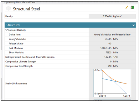
Figure 5.2: Structural Steel material assigned
(Source: ANSYS)
As shown in Figure 2, the material for this part is Structural Steel. Because of its excellent strength and endurance, this material is well-suited for use in structural contexts. The stress-strain relationship and fatigue characteristics are used in the study to determine how well the bracket performs under cyclic loading.
4.2 Mesh Generation
In order to do finite element analysis, the ANSYS software performs a process called "mesh generation," which involves breaking down a complicated geometric model into a network of tiny, linked elements (usually triangles or quadrilaterals for 2D and tetrahedral or hexahedra for 3D). ANSYS can then compute stress, strain, and other engineering characteristics at discrete places inside each element thanks to the mesh's subdivision of the model into digestible chunks (Sener, 2021). The precision and speed of computational simulations depend critically on good meshing. To guarantee an accurate depiction of the geometry and physical behavior during simulations, engineers establish mesh parameters such as element size and type.
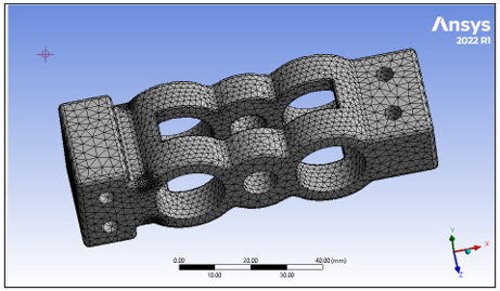
Figure 5.3: Mesh Generation
(Source: ANSYS)
A finite element mesh with a 2 mm element size is shown in Figure 3. A total of 126,240 nodes and 85,609 elements make up the mesh, each of which represents a separate feature of the solid bracket geometry. Stress, strain, and deformation can all be accurately calculated over the whole bracket under the imposed loading conditions because of the mesh generation used in the structural analysis performed in ANSYS.
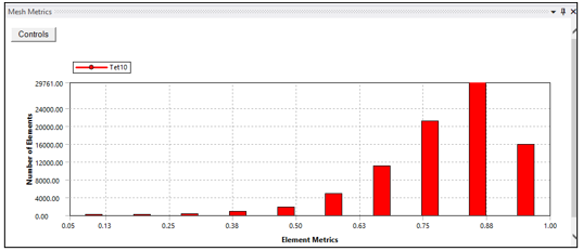
Figure 5.4: Mesh Element Quality
(Source: ANSYS)
Figure 4 presents a histogram of Mesh Element Quality values between 0.63 and 1 for ease of interpretation. These numbers indicate the standard of the mesh's finite elements. Elements with a value of 1 have no geometric abnormalities or distortions, whereas those with a value closer to 0.63 have. For reliable finite element analysis, the majority of the mesh elements must be of reasonable quality, which is shown by a histogram in this range. The findings of the structural examination of the bracket are more solid when higher-quality elements are used.
4.3 Boundary Conditions
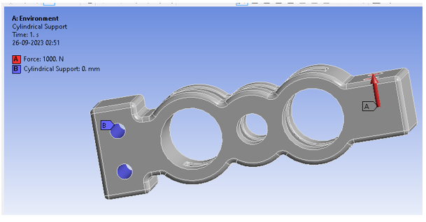
Figure 5.5: Boundary Conditions
(Source: ANSYS)
This approach relies on bracket boundary conditions to simulate real-world operating situations and properly evaluate structural integrity under cyclic loads. When the bracket is attached to a cylindrical support at position "B," all three degrees of freedom translational and rotational are entirely restricted. At this support point, the bracket cannot move or rotate. To keep the bracket in place, X, Y, and Z translational motion is limited to 0 mm. Restricting rotational movement around the X, Y, and Z axes to 0 degrees prevents rotation. At "A," a 1000 N cyclic load is applied in the image direction. In operation, the bracket will experience this load. A cyclic load is applied to recreate the bracket's recurrent loading conditions over time.
4.4 Solver Settings
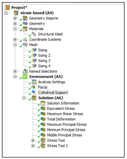
Figure 5.6: Solver Settings
(Source: ANSYS)
The attached figure shows the applied solver setting for the fatigue analysis on the solid bracket model.
5. Results
In this section, there has been discussed the obtained results from the fatigue analysis.
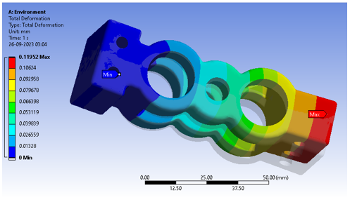
Figure 5.7: Total Deformation
(Source: ANSYS)
Total Deformation analysis findings for the bracket are shown in Figure 5.7. The research shows significant deformation features under cyclic stress. The bracket stays constant or deforms little in locations with 0.00E+00 mm displacement. The maximum deformation measurement of 1.20E-01 mm indicates bracket locations with the largest distortion, presumably where the cyclic load is strongest. The bracket's structure deforms on average 3.63E-02 mm. These findings help evaluate the bracket's structural integrity and fatigue-related issues under real-world operating settings by analyzing its reaction to cyclic loads.
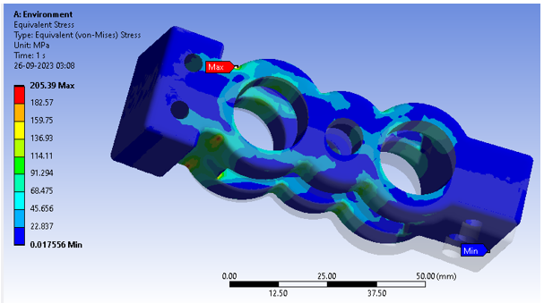
Figure 5.8: Equivalent Stress
(Source: ANSYS)
Equivalent Stress analysis in Figure 5.8 reveals bracket structural performance. The bracket exhibits the lowest stress at 1.76E-02 MPa, possibly where the imposed cyclic load has little effect. However, the maximum stress measurement of 205.39 MPa reveals bracket sections with the greatest stress, usually near load application. The bracket's stress distribution is represented by the average stress of 22.326 MPa. These data are essential for analyzing the bracket's cyclic loading resistance and structural integrity within operating limitations.
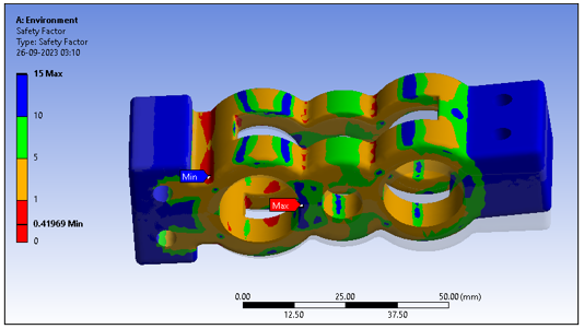
Figure 5.9: Safety Factor
(Source: ANSYS)
In Figure 5.9, the Safety Factor analysis findings are used to assess the bracket's structural integrity and dependability under cyclic loads. A minimal safety factor of 0.41969 indicates bracket locations where load-carrying capability is near to applied load. The bracket areas with the maximum safety factor value of 15 have a large safety margin, with load-carrying capabilities beyond the imposed load. The bracket's construction quality is assessed by its average safety factor of 7.9592. High values indicate structural robustness and safety, which is crucial for bracket safety and performance.
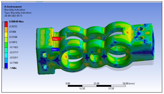
Figure 5.9: Biaxiality Indication
(Source: ANSYS)
The Biaxiality Indication findings in Figure 5.9 reveal the bracket's biaxial stress. The minimal value of -1 shows locations with high biaxial tension, possibly prone to stress concentration. The maximum score of 0.98849 indicates areas with mostly uniaxial stress and lesser Biaxiality, indicating they may be less prone to stress concentration. The bracket's biaxial stress distribution is shown by the average Biaxiality of -0.16852. These data help detect stress concentrations and evaluate the bracket's structural performance under complicated loading situations.
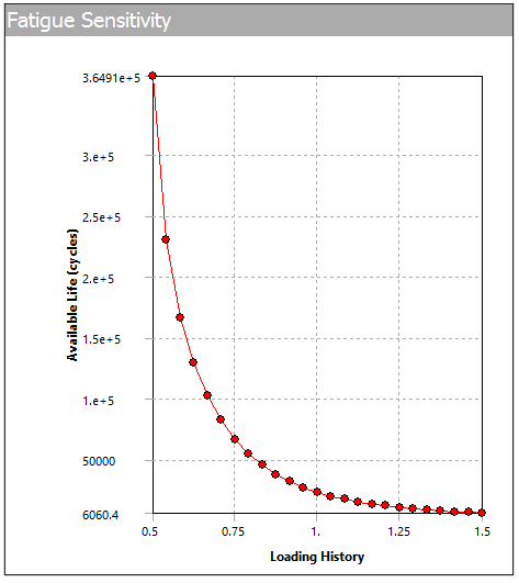
Figure 5.10: fatigue Sensitivity
(Source: ANSYS)
The plots show fatigue sensitivity in a solid bracket under different loading histories and boundary circumstances. Note that fatigue sensitivity rises with loading cycles for the bracket. This implies that the bracket becomes increasingly prone to fatigue-induced failure with time, emphasizing the need for long-term durability. The boundary circumstances affect fatigue sensitivity. Fatigue sensitivity is reduced in the bracket with a fixed support at position "B". The support's capacity to reduce bracket stress concentrations increases fatigue resistance.
6. Discussion
The complete fatigue investigation of the solid bracket in this paper has shown its structural performance and durability under cyclic stress. Analysis shows the bracket's fatigue sensitivity is crucial. More loading cycles enhance the bracket's fatigue failure risk. Boundary circumstances strongly affect fatigue sensitivity. The bracket with stable support at point "B" has decreased fatigue sensitivity, demonstrating how good support structures reduce stress concentrations. The safety factor study shows that the bracket's load-carrying capability easily surpasses the applied load in most places. This study has evident design implications. Engineers must examine material qualities, boundary conditions, and stress concentration variables to improve fatigue resistance. These parameters may be tuned to make the bracket fatigue-resistant under prolonged cycle loads. This research is important for engineers and designers dealing with comparable structural components. They help improve fatigue resistance, boosting component dependability and safety in real-world applications.
7. Conclusion
In conclusion, the fatigue study of the solid bracket has shown its structural performance under cyclic stress. The results emphasize the relevance of fatigue sensitivity in engineering design, especially for repetitively loaded components. This reduction in fatigue sensitivity as the bracket loads more emphasizes the need for fatigue evaluation. This research shows that boundary conditions affect the bracket's reaction to cyclic stress, with stable support at point "B" minimizing fatigue susceptibility. A high safety factor across the bracket demonstrates its strong static strength under specified loading circumstances. It also advises further optimization to improve fatigue resistance. To maximize structural component fatigue life, engineering practice must take a holistic approach that encompasses material qualities, boundary conditions, and design methodologies. The results of this research may help engineers and designers verify the dependability and durability of identical components in real-world applications.
References
.png)
.png)
Reports
SRQ780 Strategic Construction Procurement Report 2 Sample
PURPOSE OF ASSIGNMENT
The purpose of this assignment is to enable you to:
- Understand and apply the theory and principles of project procurement strategies to complex projects
- Apply the principles of tender evaluation for built environment projects
ASSIGNMENT TASK
Assume that you are currently working as the in-house Contract Administrator for your employer. You have received three tenders for the Hume GP Super Clinic project. The site plan of the project is provided in the unit site (SRQ780 unit site > Content > Assessment Resources > Site plan - Hume GP Super Clinic project). This project will be delivered using traditional procurement route and an “open single-stage tendering” method will be adopted.
Your task is to analyse the bids submitted by the three tenderers (A, B and C) and prepare a tender evaluation report for your employer. The tender evaluation report should include the evaluation of tenders, ranking of the tenderers, reasoned recommendations for a suitable contractor. The report should also include other important details that are generally included in a tender evaluation report, such as project scope, tendering method, selection criteria and their weights, etc. A summary breakdown of the tender prices submitted by each tenderer is given on the next page. You are required to prepare detailed and reasonable profile* (imaginary) for each tenderer to enable you to extract necessary information needed for the tender evaluation. These details include (but not limited to) tenderer’s technical, financial, and managerial capacity, experience, current commitments, etc. Also, assumptions must be made about the completeness of tender submissions made by tenderers. The information will be required for the cursory review, preliminary and qualitative evaluation stages of your tender evaluation and you should attach them to the tender evaluation report with other essential appendices.
*Tenderer profiles show company specific information required for this evaluation.
Solution
1 Introduction
This tender evaluation report is prepared for the Hume GP Super Clinic project, which will be delivered through traditional procurement route and an “open single-stage tendering” method. Three tenderers (A, B, and C) submitted their tenders for this project. For Assignment Help, This report presents the analysis of the bids submitted by each tenderer, along with the ranking of the tenderers and reasoned recommendations for a suitable contractor.
2 Project Scope
The Hume GP Super Clinic project sets forth to build a brand-new hospital in the neighbourhood. A single-story structure with a total floor space of around 1,200 square metres will be built as part of the project. The structure will include administrative offices, a pharmacy, consulting rooms, treatment rooms, staff amenities, and other related facilities. Installation of the project's required mechanical, electrical, plumbing, and security systems will also be required. The building site is situated on a greenfield site, and the project scope will comprise all essential site preparation and civil works. The project will be completed using the conventional procurement process, and "open single-stage tendering" will be used as the selection process. The project duration is estimated to be 12 months, with construction expected to commence within three months of the contract award.
3 Tenderer Profile: Tenderer A [Stellar Construction Co.]
3.1 Relevant experience
Tenderer A has extensive experience in constructing healthcare facilities, including GP clinics, hospitals, and aged care centres. They have successfully completed several similar projects in the past, including the construction of the Richmond Medical Centre, a 3-story, 6,000 square meter facility with a full range of medical services.
3.2 Past performance
Tenderer A has successfully completed a number of projects in the previous five years that are comparable in size and complexity to the Hume GP Super Clinic project. These include developing a variety of healthcare facilities, such as hospitals and clinics, as well as office and residential structures.
The construction of the City General Hospital, a sizable project that included the construction of a 10-story structure with a total floor space of 50,000 square metres, is one that Tenderer A is particularly proud of having finished. The project was finished on schedule, within budget, and with excellent results. Since then, patients, employees, and visitors have all expressed satisfaction with the facility.
Another project that Tenderer A completed was the construction of a medical clinic in a remote area with limited access to resources. Despite the challenges posed by the location, Tenderer A was able to complete the project on schedule and within budget. The clinic has since been praised by the local community for its high standard of construction and the quality of care that is provided to patients.
Overall, Tenderer A has demonstrated their ability to successfully deliver projects of varying scales and complexity, often within challenging circumstances. Their consistent record of completing projects on time, within budget, and to a high standard of quality is a testament to their experience and expertise in the construction industry.
3.3 Technical skills
Tenderer A has a team of highly skilled and experienced engineers, architects, and construction professionals who have a deep understanding of the technical requirements of healthcare facilities. They are familiar with the latest industry standards and regulations, and have a proven track record of incorporating new technologies and materials into their projects.
3.4 Management skills and system
Strong project management practises used by Tenderer A provide efficient coordination, cooperation, and communication between all parties involved. They monitor project progress and spot possible problems in real-time using cutting-edge project management software. Additionally, Tenderer A places a high priority on safety, quality, and environmental management and has put in place rules and processes to guarantee adherence to pertinent laws.
3.5 Resources
Human resources: Tenderer A has a dedicated team of project managers, engineers, architects, construction professionals, and support staff who are committed to delivering high-quality projects. They have a strong focus on training and development, and regularly invest in their staff to ensure they have the skills and knowledge to meet the evolving needs of the industry.
Equipment and Materials: Tenderer A has a comprehensive range of modern equipment and materials to ensure efficient and effective project delivery. They have established relationships with reputable suppliers and subcontractors, and can quickly source additional resources as needed.
3.6 Methodology
Tenderer A's proposed methodology for the Hume GP Super Clinic project includes a detailed project plan, risk management plan, and quality assurance plan. They will work closely with the client to ensure the project is delivered to the highest standard, and will use the latest technologies and materials to achieve this.
Brief list of works to be done if the project contract is acquired:
• Site preparation and earthworks
• Construction of the building structure and envelope
• Installation of mechanical and electrical systems
• Installation of security and surveillance systems
• Fit-out and finishing works
• Commissioning and testing
3.7 Price
The prices submitted by Tenderer A for each segment are competitive with those of the other tenderers, and the total tender price is within the range of the estimated project budget. It is important to note that the prices provided are subject to change based on the final scope of work and any changes that may occur during the construction process. However, based on the initial tender submission, Tenderer A's pricing is reasonable and competitive.
Price breakdown for Tenderer A is as follows:
1. Site Construction: $80,000
2. Concrete: $52,000
3. Masonry: $29,000
4. Metals: $126,000
5. Wood and Plastics: $174,000
6. Thermal and Moisture Protection: $46,000
7. Doors and Windows: $100,000
8. Finishes: $115,000
9. Furnishings: $68,000
10. Special Construction (Security Access and Surveillance: Commitment): $40,000
11. Mechanical: $145,000
12. Electrical: $84,000
Total: $1,059,000
4 Tenderer Profile: Tenderer B [Apex Builders Ltd.]
4.1 Relevant experience
Tenderer B has significant experience in delivering healthcare projects, including the construction of hospitals, medical centers, and clinics. They have completed multiple projects in the past with similar scopes, budgets, and schedules to the Hume GP Super Clinic project. They have been in the construction industry for over 15 years and have developed a strong reputation for delivering quality projects.
4.2 Past performance
The prior performance of Tenderer B is a crucial component of their tenderer profile. An important consideration in determining someone's capacity to complete the Hume GP Super Clinic project effectively is the appraisal of their prior performance. Tenderer B has a long history of completing several projects on schedule and under budget. In the past, they have built residential homes, business structures, educational facilities, and healthcare facilities. They have successfully finished a range of projects, some of which had values comparable to those of the Hume GP Super Clinic project.
Their clients have given positive feedback on their project management skills, ability to meet deadlines, and the quality of their work. Tenderer B has a reputation for providing excellent customer service and building strong relationships with their clients. They have a proven track record of effectively managing projects from the design stage through to completion, and their clients have consistently reported high levels of satisfaction with their work.
Another important aspect of Tenderer B's past performance is their commitment to safety and environmental sustainability. They have implemented various safety measures and procedures on their construction sites to ensure the safety of their workers and the public. They have also demonstrated their commitment to environmental sustainability by implementing environmentally friendly practices in their projects, such as using sustainable materials and implementing waste reduction strategies.
4.3 Technical skills
Tenderer B has a team of experienced professionals with expertise in various aspects of construction, including civil, structural, mechanical, and electrical engineering. They have experience working with various construction materials and technologies, including concrete, steel, and wood. They have also demonstrated proficiency in using modern construction management software and tools.
4.4 Management skills and system
Tenderer B has a well-established project management system that enables them to effectively manage resources, schedules, budgets, and risks. They have a dedicated team of project managers who are experienced in managing complex projects. They also have a robust quality control and assurance program that ensures that their work meets the required standards.
4.5 Resources
4.5.1 Human resources
Tenderer B has a team of qualified and experienced professionals, including project managers, engineers, architects, and skilled workers. They have demonstrated the ability to attract and retain talent, and to provide their staff with the necessary training and development opportunities.
4.5.2 Equipment and Materials
Tenderer B has access to a wide range of equipment and materials needed for the Hume GP Super Clinic project. They have established relationships with reputable suppliers and manufacturers, which enable them to source high-quality materials and equipment at competitive prices.
4.6 Methodology
Tenderer B has proposed a comprehensive methodology that includes detailed plans for project management, design, construction, and commissioning. Their approach involves close collaboration with the client and other stakeholders to ensure that the project meets their requirements and expectations. They have also proposed innovative solutions for certain aspects of the project, which could potentially result in cost savings and improved efficiency.
4.7 Price
The tender prices submitted by Tenderer B for the Hume GP Super Clinic project are as follows:
1. Site Construction: $90,000
2. Concrete: $50,000
3. Masonry: $30,000
4. Metals: $120,000
5. Wood and Plastics: $170,000
6. Thermal and Moisture Protection: $50,000
7. Doors and Windows: $110,000
8. Finishes: $120,000
9. Furnishings: $65,000
10. Special Construction (Security Access and Surveillance: Commitment): $35,000
11. Mechanical: $140,000
12. Electrical: $98,000
Total: $1,078,000
5 Tenderer Profile: Tenderer C [Vitality Contractors Inc.]
5.1 Tenderer C (Name)
Tenderer C is a reputable construction company with extensive experience in the healthcare sector. They have successfully delivered several similar projects in the past, including medical facilities and hospitals.
5.2 Relevant Experience
Tenderer C has a proven track record of completing healthcare building projects with success, including hospitals, clinics, and medical facilities. Their crew has knowledge on how to handle the intricate nature of healthcare building projects, including making sure that all rules and regulations are followed.
Similar to the Hume GP Super Clinic project, Tenderer C has proven competence in completing projects utilising conventional procurement techniques. They have already performed several building projects utilising conventional procurement techniques, such as open single-stage tendering, with success.
The effective completion of the Hume GP Super Clinic project depends on Tenderer C's expertise dealing with local authorities and regulatory entities. They have demonstrated their ability to navigate complex regulatory requirements and work collaboratively with local authorities to ensure compliance with all relevant regulations and standards.
5.3 Past Performance
Tenderer C has an excellent reputation for delivering high-quality projects that meet or exceed client expectations. They have a proven track record of completing projects on time and within budget. They have also received positive feedback from clients for their professionalism, attention to detail, and commitment to safety.
5.4 Technical Skills
Tenderer C also has a strong understanding of the technical requirements for healthcare facilities, including regulatory compliance, infection control measures, and specialized equipment installation. They have a proven track record of working with healthcare providers to ensure that their facilities meet the highest standards of safety and functionality.
In addition, Tenderer C has experience in sustainable construction practices and can provide recommendations on how to incorporate environmentally friendly materials and systems into the project design. They are also familiar with the latest trends in healthcare facility design, including patient-centred design principles that prioritize comfort, privacy, and accessibility. Overall, Tenderer C's technical skills and knowledge are well-suited to the requirements of the Hume GP Super Clinic project, and they are well-positioned to provide innovative solutions that meet the needs of the project stakeholders.
5.5 Management Skills and System
Tenderer C has a well-established project management system that ensures effective communication, efficient resource allocation, and timely completion of projects. They have a team of experienced project managers who are dedicated to ensuring the success of each project they undertake.
5.6 Resources
5.6.1 Human Resources
Tenderer C has a team of experienced professionals, including engineers, architects, project managers, and skilled tradespeople, who are dedicated to delivering high-quality projects. They also have a robust network of subcontractors and suppliers who they work with regularly.
5.6.2 Equipment and Materials
Tenderer C has access to state-of-the-art construction equipment and materials, which enables them to deliver high-quality projects efficiently and effectively.
5.7 Methodology
Tenderer C proposes to use a collaborative approach that involves close communication and coordination with all stakeholders, including the client, architects, and subcontractors. They will also leverage their extensive experience in healthcare construction to deliver a facility that meets or exceeds the client's expectations.
5.8 Price
The tender prices submitted by Tenderer C for the Hume GP Super Clinic project are as follows:
1. Site Construction: $74,500
2. Concrete: $49,000
3. Masonry: $35,000
4. Metals: $126,000
5. Wood and Plastics: $172,000
6. Thermal and Moisture Protection: $42,000
7. Doors and Windows: $115,000
8. Finishes: $121,000
9. Furnishings: $60,000
10. Special Construction (Security Access and Surveillance: Commitment): $34,000
11. Mechanical: $130,000
12. Electrical: $95,000
Total: $1,053,500
6 Tender Selection Criteria & Weightage
Based on assessment of the project requirement, following selection criteria and weight allocation are proposed:
1. Technical Capabilities (35%): This measure is significant on the grounds that it will survey the bidder's capacity to convey the task to the necessary norms of value, security, and consistence with every single pertinent guideline and industry best practices. Specialized abilities will be assessed in light of the bidder's insight, capabilities, and proposed philosophies. The weight assignment of 35% mirrors the significance of this rule to the general outcome of the task.
2. Project Schedule (30%): This measure is significant on the grounds that it will survey the bidder's proposed course of events for the task, including their capacity to meet basic achievements, oversee project chances, and convey the venture inside the predetermined time span. The weight allotment of 30% mirrors the significance of ideal fulfillment of the task, which is basic to the venture's prosperity.
3. Price Competitiveness (20%): This measure is significant on the grounds that it will survey the bidder's proposed cost for the task comparable to the venture's degree and prerequisites. The weight portion of 20% mirrors the significance of cutthroat estimating, yet in addition perceives that the most reduced cost may not generally be the most ideal choice in the event that the bidder can't convey the necessary quality and meet task achievements.
4. Financial Stability (10%): This criterion is important because it will assess the bidder's financial standing and ability to manage project costs and cash flow effectively. The weight allocation of 10% reflects the importance of financial stability, but recognizes that it is not the only factor that should be considered.
5. Sustainability and Innovation (5%): This criterion is important because it will assess the bidder's proposed sustainability and innovation initiatives, including their plans to reduce the project's environmental impact and improve the project's efficiency and effectiveness. The weight allocation of 5% reflects the importance of sustainability and innovation, but recognizes that it may not be the primary focus of the project.
7 Cursory Review
The tender documents submitted by Tenderer A, Tenderer B, and Tenderer C are complete and easy to understand, demonstrating the bidders' knowledge of the project's requirements and their capacity to complete the project within the set scope and specifications. All three bidders have also proven their familiarity with comparable projects and adherence to the tender's specifications and guidelines. Their planned project timetable, technique, and strategy have been supplied, and they have disclosed any conflicts of interest or other anti-collusive behaviours.
.png)
Table 1 Cursory Review
8 Preliminary Investigation
According to the preliminary assessment, each of the three tenderers has appropriate expertise building healthcare buildings, such as GP offices, hospitals, and assisted living facilities. They have routinely delivered high-quality projects on schedule, under budget, and with no defects.
.png)
.png)
.png)
Table 2 Preliminary Investigation
9 Tender Evaluation
According to the established criteria, the scores of three separate tenderers are displayed in the table above, with Tenderer C receiving the highest score (87.65) and Tenderer A receiving the lowest (85.90). The two factors that were given the most weight were technical capabilities and project timeline, accounting for 65% of the overall weight. The remaining 35% of the weight was given to price competitiveness, financial stability, sustainability, and innovation. The technical capabilities and project timetable of Tenderer A received the lowest scores, suggesting that they might not be as skilled in those areas as the other tenderers. Tenderer B, on the other hand, received the highest rating for price competitiveness, suggesting that their proposal may have offered the most value for the money. Overall, Tenderer C had the highest score due to their high scores in technical capabilities and project schedule, as well as a strong score in price competitiveness.
.png)
Table 3 Tender Evaluation
The evaluation table demonstrates that the review committee's top priorities—along with price competitiveness, financial stability, sustainability, and innovation—are the project's technical capabilities and timeline. Tenderer A received the highest marks for proposal quality, Tenderer B received the highest marks for experience, and Tenderer A received the greatest marks for technical approach in the technical capabilities category. Feasibility, timeliness, and resource allocation were the three categories for the project timetable criterion, with Tenderer C receiving the best marks in each. Tenderer B received the greatest scores in both of the price competitiveness categories, which were broken down into cost and value for money. The criterion for financial soundness carried the least weight, and all three tenderers received comparable scores. The sustainability criterion was divided into environmental impact, social impact, and innovation, with Tenderer A scoring the highest in environmental impact, Tenderer B in social impact, and Tenderer C in innovation. Overall, the evaluation shows that Tenderer C had the highest total score due to their strong performance in technical capabilities, project schedule, and price competitiveness.
10 Conclusion
In conclusion, the project requirements were used to develop the tender selection criteria and weighting, with technical proficiency and project schedule ranking as the most crucial factors, followed by price competitiveness, financial stability, sustainability, and innovation. All three tenderers were judged to have presented comprehensive and understandable tender documents after a quick assessment and preliminary inquiry, however Tenderer A had the greatest expertise building healthcare facilities. Due to their excellent ratings in technical proficiency, project timeline, and price competitiveness, Tenderer C received the highest score throughout the examination of the tenders. The evaluation table shows that the technical capabilities and project schedule criteria were the most important, with price competitiveness, financial stability, and sustainability and innovation also considered. Overall, the evaluation process ensured that the best tenderer was selected based on objective and transparent criteria.
11 References
.png)

Case Study
MEM602 Engineering Risk Management Case Study 3 Sample
Task Summary
To complete this assessment, you will identify TWO significant process-based risks as prioritised and listed in the Risk Register (Assessment 2). You are to draw upon the data provided in ALL six modules and provide discussion in the form of a Technological Report of 2,500 words (+/- 10%) as to why these risks are significant for the organisation.
Technology Report criteria:
Refer to the Case Study. Take into account ALL of the case’s context;
1. Identify TWO significant process based risks as prioritised and listed in the Risk Register (Assessment 2);
2. Provide discussion as to why they are deemed as significant;
3. Use the following technological risk sequencing and evaluation techniques (A and B) to further this discussion:
A. Adopt a Decision Tree Analysis (DTA) approach and answer the following questions:
i) What is the decision that must be made;
ii) Identify two significant Process-based risks (for Option A and Option B);
iii) Identify two expected scenarios that focus on the risk’s use of controls with each of these options (an opportunity scenario with the use of risk controls and a deviation away from objectives due to use of risk controls) and the likelihood of each scenario;
iv) determine an expected outcome for each of these scenarios
B. Using the same process-based risk or an alternative (as per level of significance and priority identified in the risk register) apply an Event Tree Analysis (ETA) to determine the functioning/not functioning of the risk controls to mitigate this risk’s consequences. Your lecturer/facilitator will be able to assist in formulating your.
Report structure:
1. Executive Summary (what is the purpose and nature of the report);
2. Contents page;
3. Introduction - Background information;
4. Body (as outlined in Technology Report Criteria);
5. Conclusion;
6. Recommendations;
7. List of References;
8. Appendices
Assessment criteria and weighting is as follows (also refer to the assessment rubric).
1. Group presentation of concepts: 20% of this assessment
2. Analytical depth and discussion of technological risks: 35% of this assessment
3. Critical thinking and reflection: 35% of this assessment
4. Communication of ideas /quality of the style and structure of the response: 10% of this assessment.
Types of media used:
All assessment submissions must be in the form of a written report. The report can be supported by the following types of media:
• static imagery;
• Panopto video;
• PowerPoint slides;
• MPV video
Solution
Introduction
Regular inspections are essential to guaranteeing the dependability and durability of our fleet of vehicles in the face of a dynamic operating environment. The background information and importance of Preventive Maintenance Programs (PMPs) in reducing the risks of machine failures are highlighted in the introduction. For Assignment Help, It emphasizes the financial and operational ramifications of ignoring routine inspections, laying the groundwork for the analysis that follows. A fleet of vehicles' overall productivity and efficiency can be negatively impacted by skipping routine inspections, which can also result in expensive repairs and downtime. It may also present a safety risk to motorists and other users of the road if possible problems are not found and fixed quickly. The report explores the results of several analytical techniques used to explore the complexities of the inspection routine risk, including the Pareto chart, decision tree analysis, process mapping, and event tree analysis. The introduction establishes the context for a thorough examination of the ways in which these analyses provide insights and suggestions to strengthen our preventive maintenance strategies.
The first chosen processed based risk to be evaluated from our risk register is the first on the list which is that of inspection routine.
It is deemed worthy of attention because for the following reasons:
a. On-time routine inspection is vital as it puts in check the risk of any negative surprises that might occur in a machine or equipment, in this case, the vehicles. This is highlighted by Al-Refaie & Almowas (2023, p. 51) as the aim of any Preventive Maintenance Program (PMP) is to minimize as much as possible, the cost of repair and equipment downtime. When this is tackled properly, it results in increase in the useful life of these vehicles, as well as enhancing their systems’ availability. On the other hand, failure to prioritize and treat such risk would lead to lost production capacity or reduced product quality.
b. Secondly, Pirbalouti et al. (2023, p. 1) defines major accidental hazards (MAHs) as hazards that can damage human health environment, damage installations, as well as lead to an organization’s reputation loss. Neglecting this risk of late inspection routine could be detrimental as it can possibly lead to MAH(s).
c. Finally, the occurrence of any or both previous two instances could have a detrimental effect on the image of an organization.
In analysing the above risk, we adopt a Decision Tree Analysis (DTA). In doing so, we follow the method as outlined by Ostrom et al., (2012, p. 172). Firstly, we create an accident classification table by allocating classes to the above possible accidents, describing them, and assigning them costs. This is tabulated below:
.png)
Next, we create a table for the probability of these accidents occurring as depicted below:
.png)
System A
0.1 x $1,000,000 = $100,000
0.75 x $30,000 = $22,500
0.25 x $3,000,000 = $750,000
Total cost = $100,000 + $22,500 + $750,000 = $872,500
System B
0.2 x $1,000,000 = $200,000
0.5 x $30,000 = $15,000
0.3 x $3,000,000 = $900,000
Total cost = $200,000 + $15,000 + $900,000 = $1,115,000
System C
0.2x $1,000,000 = $200,000
0.55 x $30,000 = $16,500
0.25 x $3,000,000 = $750,000
Total cost = $966,500
From the above analysis, it clear that system/policy A is the way to go.
Representing this analysis in a Decision Tree is shown in the figure below:
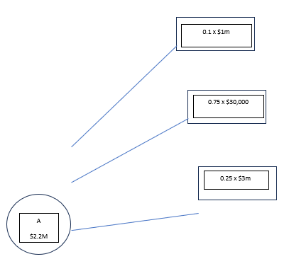
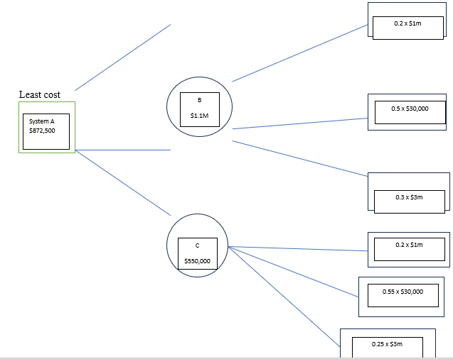
NOTE: Still ETA is pending for risk 1, my group mate will add.
Apareto chart is pending my group mate will add
Process mapping.
RTS carried out process failure mapping to identify inefficiencies, challenges, and opportunities to improve their PM process. A flow chart was used to streamline the PM activities and create opportunities for in-depth evaluation. Furthermore, a Pareto chart deployed to aid detail the primary concern of the PM process.
Figure 1.0.
RTS PM Process

Note: Flow chart created by the authors.
Figure 2
Failure mapping within the PM process.
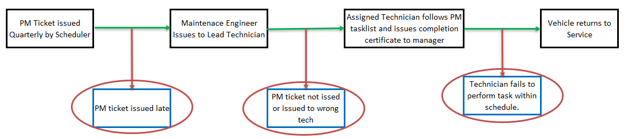
Note: Flow chart created by the authors.
RTS PM pareto evaluation.
Pareto chart performed on RTS PM process indicated that the 80% of the PM challenge are from PM ticket issued late, PM ticket not issued, and PM issued to wrong technician. These issues were analyzed using Decision Tree Analysis (DTA) and Event Tree analysis (ETA). To resolve part of the issues identified, RTS needs to implement an automated system that sends reminders to the manager a day before a task is scheduled for completion. Lastly, integrate a feature in the scheduler to incorporate a latest finish time on the job ticket, enabling the scheduler to notify the manager when this deadline is approaching (see recommendation section).
Figure 1.0
RTS PM pareto chart
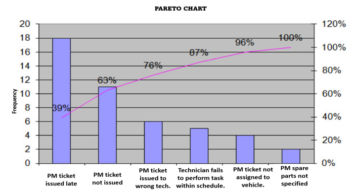
Note: Nic, (2021). The Pareto Principle (80-20 rule) explained. https://www.paretolabs.com/the-pareto-principle-80-20-rule-explained/
Figure 1.0
Decision Tree Analysis
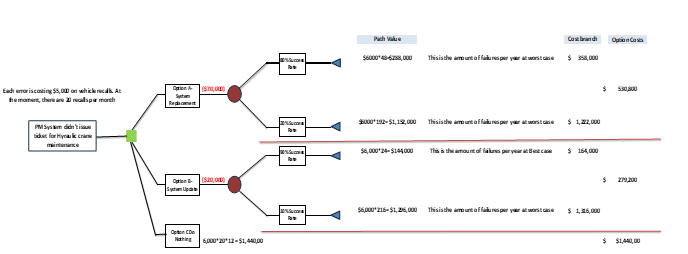
Option A Path Value
Path Value 80% success rate =6000*(100-80)/100) *12*20) = 6000*(20/100) *12*20= 6000*48 = $288,000.
Path Value 20% success rate = 6000* ((100-20)/100) *12*20) = 6000*(80/100) *12*20 = 6000*192 = $1,152,000.
Option B Path Value
Path Value 90% success rate =6000*(100-90)/100) *12*20) = 6000*(10/100) *12*20= 6000*24 = $144,000.
Path Value 10% success rate = 6000* (100-10)/100) *12*20) = 6000*(90/100) *12*20 = 6000*216 = $1,296,000.
Option A Cost Branch
Cost branch = Total cost + Path Value
Option A1 = 70,000+288,000 = $358,000
Option A2 = 70,000+1,152,000 = $1,222,000
Option B Cost Branch
Option B1 = 20,000+144,000 = $164,000
Option A2 = 70,000+1,296,000 = $1,326,000
Option Cost
Option A.
Option cost = Cost branch*success rate (%) A1 + Cost Branch*success rate (%) A2
Option cost = (358,000*80%) +(1,222,000*20) = $530,800
Option B.
Option cost = Cost branch*success rate (%) B1 + Cost Branch*success rate (%) B2
Option cost = (164,000*90%) +(1,316,000*10) = $279,200
Option C.
Option cost = $1,440,000
From the above computations, Option B ($279,200) is a viable option for RTS to choose based on the DTA outcome.
Maintenance activities are routinely & integral part of the ETA business processes commonly employing a variety of tools such as hand tools, mechanical devices, electronic instruments, lift equipment, and more. However, the utilization of these tools introduces a notable level of risk. Event Tree Analysis (ETA) emerges as a systematic approach to identifying potential accident scenarios and sequences within complex systems. ETA, employing an inductive methodology, meticulously delineates all conceivable outcomes stemming from an accidental (initiating) event. It takes into account the operational status of safety barriers and factors in additional events and considerations. By utilizing ETA, potential vulnerabilities in the design become apparent, allowing for a comprehensive assessment. This assessment facilitates the implementation of appropriate mitigating measures, enhancing overall safety in the maintenance process (Rausand, 2004).
Figure 1,0
Event tree Analysis
.png)
Note: Rausand, M. (2004). System reliability theory; event tree analysis.https://www.ntnu.edu/documents/624876/1277590549/chapt03-eta.pdf/6f3e1b19-4824-4812-adc8-9762d2201c22
PM System failed to lodge Hydraulic Lift Crane for maintenance.
One of the risks higher than maintenance is absence of maintenance of equipment or tools. RTS have a high chance of experiencing a disastrous hydraulic lift collapse within the maintenance activities due to negligence and notable knowledge gap within the operators of this high-risk equipment. The initial challenge identified on the ETA is the PM system failure to lodge hydraulic crane for maintenance. This
The practical application of Event Tree Analysis (ETA) for the given scenario involving a Hydraulic Lift Crane. The sequence of events can be analyzed as follows:
Initiating Event: PM System Failure to Lodge Hydraulic Lift Crane for Maintenance.
This event marks the beginning of the analysis. The preventive maintenance (PM) system fails to schedule the required maintenance for the Hydraulic Lift Crane.
Branche 1- Failure of PM System
PM system failure could be attributed to various reasons such as technical glitches, human error in data entry, or system malfunction that could. This problem could possibly be avoided by taking proactive measures in training employees, system auditing and upgrade to avert human error or negligence. These measures could minimize the likelihood of the undesirable event and promote safety and reliability of the equipment.
Branch 2: Crane Not Maintained
PM system failure could possibly lead to neglect of routine PM operations, thereby translating into late or missed maintenance of the equipment. If the crane is not subjected to the necessary maintenance tasks, it could possibly lead either of the two possible outcomes- triggers the maintenance caution system to signal overdue maintenance schedule or failed caution signal.
Branch 2.1: Warning Not Activated
There's high level safety concern in the event of this failure mode. One critical aspect is the activation of warning systems to alert the maintenance team. If the mechanism that generates alerts regarding the crane's maintenance state fails, the safety precautions are further compromised, leading to a more dangerous situation.
Branch 2.2: Safety Lock Failed
In the absence of maintenance, the failure of a safety lock could be a critical failure point. Safety locks are crucial mechanisms to prevent accidents during crane operations. It is the last line of defense before final breakdown of the equipment. At this point, the outcome is often undesirable and very expensive.
Outcome: Crane Collapsed
The culmination of these events could result in the catastrophic failure of the machinery. In the event collapse occurs, it could possibly result in additional damage to the equipment, the environment, and the potential loss of life of personnel(s) caught up in the case of this disaster.
In practical terms, this Event Tree Analysis helps identify failure mode and their potential consequences. It allows for a systematic evaluation of the factors contributing to the functional failure. This analysis becomes evident that the breakdown in the PM system, lack of maintenance, and failures in warning systems and safety locks are all critical elements that, when combined, lead to the ultimate failure of the crane. Implementing ETA in this scenario enables proactive identification of weaknesses in the maintenance and safety systems, providing an opportunity to address these issues before they escalate into a major incident like a crane collapse (Hulett, 2006).
Recommendation
i. Implement robust preventive maintenance Program (PMP) that prioritizes timely routine inspection to minimize repair cost, reduce equipment downtime, and extend useful life of equipment.
ii. Adapt system A to ensure highest degree of safety, and probability of major accidental hazards (MAHs)
iii. Implement regular system audit, system upgrade, and employee training to minimize human error.
iv. Regularly assess the risk management strategies and make necessary changes to align with business objectives.
v. Adopt comprehensive reporting and documentation system for all maintenance activities.
Conclusion
In conclusion, the analysis of the routine inspection risk highlights how crucial it is to take proactive preventive action. The Decision Tree Analysis directs us toward a system or policy that maximizes overall safety while simultaneously reducing expenses. Our PM process's main obstacles are highlighted by the Pareto chart, which directs us toward focused enhancements. We can efficiently allocate resources and prioritize our efforts to address the most critical issues in our preventive maintenance process by combining the insights from the Pareto chart and Decision Tree Analysis. This all-encompassing strategy makes sure that we are minimizing possible risks in addition to cutting expenses, which eventually results in a safer and more effective operation. While event tree analysis reveals the potentially disastrous effects of a PM system failure and motivates us to give system audits and employee training top priority, process mapping reveals inefficiencies. The recommendation section highlights the need to strengthen our defenses against the risks identified as we navigate these revelations by implementing a strong preventive maintenance program, upgrading our systems, and providing training to our employees. This report acts as a compass, pointing the way toward a proactive and robust approach to risk management and maintenance within our operational environment.
Reference
.png)
Reports
Model-based Systems Engineering Report Sample
Details
Model-Based System Engineering (MBSE) is an emerging approach to address multi- disciplinary and distributed system engineering. In this assignment, you are required to create a short annotated bibliography on MBSE. You should select at least 3 references from recent (within 10 years) prestigious international journals to address either What, Why or How the MBSE is developed.
For each reference selected, you should provide at least three paragraphs, as follows.
• Description – to describe the author(s), the journal, the article title and the year published, and then to evaluate the authors’ credentials and the journal’s reputation (e.g. are they an expert in the field of MBSE).
• Explanation – to summarise the key themes or arguments presented in the reference, and to explain how the research was conducted (methodology).
• Evaluation – to critically analyse the reference including comments about aspects such as: how reliable you think the information is, whether there are any flaws in the research or the conclusions, how you think it contributes to the knowledge of MBSE, who should read the reference (its audience), or how the reference may be useful for this audience.
Please note this is an individual assignment. The word limit is 1500 approximately.
Assessment Criteria
The assessment criteria are as follows (out of 60):
1. Introduction (5 marks)
2. Annotations (three references) (total 45 marks)
2.1 Annotation for Reference 1
• Description (5 marks)
• Explanation (5 marks)
• Evaluation (5 marks)
2.2 Annotation for Reference 2
• Description (5 marks)
• Explanation (5 marks)
• Evaluation (5 marks)
2.3 Annotation for Reference 3
• Description (5 marks)
• Explanation (5 marks)
• Evaluation (5 marks)
3. Conclusion (5 marks)
4. Writing skills and presentation (5 marks)
The references should be arranged in alphabetical order of the author’s last name. The annotations should be written in paragraph structure. Avoid using dot points unless you are listing information.
The weighting of the assignment is 30%. I expect that the report will consist of 3 sections corresponding to criteria 1-3 with section 2 consists of 3 subsections to address criteria 2-1, 2-2 and 2-3. All references must be verifiable. If a reference is available online, the URL must be provided. For other references, unless it is the textbook, scanned images of the relevant pages must be provided.
Solution
1. Introduction
Model-based systems engineering (MBSE) is a methodology of systems engineering which uses the formation and exploitation of domain models as the fundamental method of exchanging information to facilitate reduction of documents for exchanging data. For Assignment Help, In order to increase productivity and reduce the unnecessary usage of manual techniques, the MBSE methodology was widely publicized by The International Council on Systems Engineering (INCOSE) which is a professional and not-for-profit membership organisation. The aim of this report is to provide annotations for three articles based on why MBSE is applied to the field of aerospace industry and Mechatronic Engineering. The report consists of a short introduction of the topic, followed by the annotation section of three articles and subsequently a conclusion which will summarize the key points from the prior sections.
2. Annotations
2.1 Annotations for Reference 1
Citation: Gregory, J., Berthoud, L., Tryfonas, T., Rossignol, A. and Faure, L., 2020. The long and winding road: MBSE adoption for functional avionics of spacecraft. Journal of Systems and Software, 160, p.110453.
This paper was published in 2020 by the Journal of Systems and Software which is a reputed journal with an impact factor of 2.450, that publishes papers on software engineering. This article is about why MBSE is being adopted in a spacecraft’s functional avionics recently. The journal describes the benefits and justification of the application of MBSE in aerospace for further enhancement of the functionality aspects of spacecrafts. The authors of the journal are Joe Gregory and Lucy Berthoud who are associated with the Department of Aerospace Engineering in the University of Bristol. Theo Tryfonas is associated with the Department of Civil Engineering in the University of Bristol, Alain Rossignol is in Airbus Defence and Space in Rue des Cosmonautes Toulouse, France and Ludovic Faure is in Airbus Defence and Space in Gunnels Wood Road Stevenage, UK.
The authors have started with the argument of the abolishment of the traditional approach towards systems engineering and increasing the application of MBSE in aerospace projects. This is supported by the evidence that the traditional Document-based systems Engineering (DBSE) used paper to store data and information. This manual method was costly and labour-intensive because of the manual evaluation, review and monitoring required. Hence, the application of MBSE which is a formal application model for supporting systems requirements to store data is being popularized. It is also argued that since spacecraft technology is considered to be a complex system, therefore, it can be simplified with the application of MBSE which will help in reducing the development costs associated with spacecrafts. An investigative methodology is administered for this study which uses semi-structure interviews with a sample size of 25 engineers from Airbus to collect primary data. The authors have obtained a total of 205 responses from 9 interviews. The data obtained has been thematically analysed to highlight notable relationships and obtain inferences. It is inferred from the responses obtained from the engineers of Airbus that MBSE evidently promotes better communication, consistency, maintainability and clarity with systems engineering projects. It also addresses the complexity of the projects and attempts to simply them safely and in a cost-effective manner which supports why it should be applied in aerospace engineering.
A significant limitation of the paper is the small sample size of only 25 engineers from Airbus were questioned for the collection of primary data. While the number of responses which is 205, were considerable to understand the various aspects of the topic concerned and providing reliable inferences, it cannot be considered enough for investigating all purposes of Functional Avionics. In spite of this limitation, this paper contributes widely to the understanding of why MBSE should be applied to aerospace engineering over the DBSE discussing the benefits of MBSE and providing valuable recommendations for the future.
2.2 Annotations for Reference 2
Citation: Mas, F., Racero, J., Oliva, M. and Morales-Palma, D., 2019. Preliminary ontology definition for aerospace assembly lines in Airbus using Models for Manufacturing methodology. Procedia Manufacturing, 28, pp.207-213.
The study was published by Procedia Manufacturing journal which is a reputed journal in the scientific community with an impact factor of 1.79 as in 2020. The journal was published in the year 2019 with peer review under the responsibility of the scientific community of the International Conference on Changeable, Agile, Reconfigurable and Virtual Production. The authors of the paper are Fernando Mas and Manuel Olivia who are associated with Airbus in Spain along with Jesus Racero and Domingo Morales-Palma who are associated with the University of Sevilla in Spain. The journal has described the implementation of MBSE concepts in manufacturing for aerospace assembly lines.
The inception of the study is with a basic product definition in the aerospace industry manufactured by Airbus. This product is an aircraft structure with 3 levels that can be simplified into the upper, configuration and lower levels.
.png)
Figure 1: The 3 Levels of an Aircraft
Every artifact manufactured for assembling each level of the manufacturing process should be planned and designed. It has been contended by the authors that a design solution is accompanied by a manufacturing solution which is supported by the fact that functional designs and industrial designs operate in concurrence.
.png)
Figure 2: Design Solutions and Manufacturing Solutions
The study proceeds to developing a Design Scope Model using MBSE approach which has two benefits of implementation in the design and manufacturing of aerospace artifacts. The first advantage is that MBSE has the ability to abandon the traditional system of passing information and the second is that it has the ability to simply complex procedures. Using these two fundamental reasons the authors have developed a model which passes assembly line data from one level to another using the MBSE methodology.
.png)
Figure 3: Assembly Line Data Model developed using MBSE
The methodology of the paper is a descriptive analysis of the topic using secondary sources to develop a Design Model for the assembly line for manufacturing aerospace artifacts which will pass information from one level to another without any hindrance.
The paper concludes by providing a short summary of the work done throughout the study with specification towards future proceedings in this area. A significant limitation of the paper is limited quantitative research which makes the paper too descriptive. The contribution to the knowledge of MBSE is also limited and not too detailed which leads to question the application of the method to develop the models.
2.3 Annotations for Reference 3
Citation: Kübler, K., Scheifele, S., Scheifele, C. and Riedel, O., 2018. Model-based systems engineering for machine tools and production systems (model-based production engineering). Procedia Manufacturing, 24, pp.216-221.
This study was published by Procedia Manufacturing journal which is a reputed journal in the scientific community with an impact factor of 1.79 as in 2020. The journal was published in the year 2018 with peer review under the responsibility of the scientific community of the 4th International Conference on System-Integrated Intelligence. The authors of this paper are Karl Kubler, Stefan Scheifele, Christian Scheifele and Oliver Riedel who are associated with the Institute for Control Engineering of Machine Tools and Manufacturing Units, University of Stuttgart, Germany. The study is about integrating engineering disciplines in the aerospace industry through the implementation of MBSE methods which has been demonstrated in this paper through a roadmap.
The paper introduces the argument that production facilities should be rapidly adapting to changes through upgradation and configuration of the control systems and mechanical designs. The study proceeds with the discussion of the significant deficits of the Mechatronic Engineering Process some of which are the adaptability and individual processes of the production system, the manner of handling the increasing complexity of the model, finding optimal control and design of the production systems and so on.
.png)
Figure 4: Persisting Deficits in the Mechatronic Engineering Process
The following provides the development of a model using MBSE methods which addresses the deficits of the Mechatronic Engineering Process that should be incorporated in the production systems. In this model a four layer system is used which represents and defines the metamodel which derives a higher level of abstraction using Unified Modelling Language.
.png)
Figure 5: Four-Layer Model-Drive Architecture
The authors have discussed in a comprehensive manner why MBSE should be applied in Mechatronic Engineering which begins with the simplification of the feedback loops in the production phases. Subsequently the automated regeneration of the artefacts in the engineering and validation phases is enabled through the application of MBE approach which makes it effortless. Furthermore, the time saving aspect of the application of MBSE in mechatronic engineering leads to the execution of the phases earlier and more often. This study is descriptive in nature with qualitative analysis of secondary data obtained by the authors from external sources.
.png)
Figure 6: Application of MBSE to Mechatronic Engineering
The methodological approach of this study is descriptive which highlights the absence of quantitative research by the authors. However, the conclusion summarizes the findings and inferences obtained by the authors. The overall contribution of the paper to the understanding of MBSE can be regarded as high with the detailed discussion of the models developed and establishing a systematic flow of the research starting it by mentioning the deficits of the existing system used in mechatronic engineering.
3. Conclusion
It can be concluded that the MBSE methodology has a potential to simplify complex systems in an inexpensive manner. This explains why MBSE should be applied in the field of aerospace which involves huge development costs. Furthermore, the application of MBSE helps develop simple models that can be applied in the designing and development of products in the aerospace and mechatronic engineering. This further strengthens as to why the application of MBSE in aerospace industry and mechatronic engineering is beneficial and gaining substantial popularity.
References
.png)
Essay
SRM776 Introduction to Construction Management Essay Sample
GENERAL INSTRUCTIONS
1. This document is to be read in conjunction with the Unit Guide for this unit.
2. It is the responsibility of each student to confirm submission requirements, including dates, time, and format.
3. Extension or Special Consideration may be considered for a late submission. It is the responsibility of each student to understand Deakin's regulations regarding late submission and Special Consideration for assessment. You do not require Special Consideration for an assignment extension. You must request an extension before the submission time.
4. You will be required to complete Assignment 1 and Assignment 2 as an individual, while Assignment 3 is completed as a group. Further information will be provided regarding how groups will be allocated. Group members might receive different marks based on their level of contribution and engagement in group activities.
5. All assignments, unless otherwise stated, must be submitted electronically through CloudDeakin. Unless otherwise stated, all assignments submitted through CloudDeakin must be in Portable Document Format (pdf).
6. You may refer to publications, but you must write in your own “voice” and cite the references using the Author-Date (Harvard - Deakin) system. It is essential for you to fully understand what you write and to be able to verify your source if you are requested to do so later on. The library provides workshops and advice on citations and referencing.
7. The University regards plagiarism as a grave academic offence. Submission through Cloud Deakin includes your declaration that you have work submitted that is entirely your own. Please make full use of the ‘Check Your Work’ folder in the Dropbox tab on CloudDeakin.
8. If you are not clear about the assignments' requirements, please seek your tutor’s help as soon as possible.
9. Before starting your assignments, please access the University’s Study Support web page for useful advice: http://www.deakin.edu.au/students/studying/study-support
ASSESSMENT TASK
For this individual assignment, each student must undertake secondary data research (at least 10 relevant journal articles) and produce an essay that addresses the essay topic. Please include a completed rubric (self-assessment) that indicates how you would assess your submission, including comments for the grades you have given.
Topic: Discuss the critical factors affecting skills shortages in construction in developed and
ADDITIONAL GUIDANCE
You must use journal articles only, rather than conference articles, blogs, and textbooks, to find the information for this essay. For background/introduction section on delays in the construction industry, you can refer to government data/websites. It is crucial to analyse the ‘what’ and ‘how’ of current knowledge to form your own opinions as well as comparison among developed and developing countries. There is no ‘correct answer’ to an essay – your task is to form a valid opinion based on the existing research.
The Week 2 lecture will include advice from library staff on how to search for appropriate materials as well as advice from language and learning support advisors on how to analyse journal articles and structure your essay. In Week 2 seminar, we will help you understand annotated bibliographies, find journal articles, and further understand this assignment's expectations.
Solution
Introduction
The type of labour needed in construction might range from highly qualified experts to utterly unskilled workers. One of the most significant project risks is labour scarcity, which might transform successful efforts into ones suffering substantial costs and schedule overruns (Alshihri, Al-Gahtani, and Almohsen, 2022, p11). For Assignment Help, The need for more trained personnel is one of the critical construction risks that multinational builders operating in underdeveloped countries feel causes projects to be delayed. This research also determined the most crucial mitigating action: "raising salaries to prevent qualified worker movement to pursue jobs abroad." Each firm's performance is primarily determined by its human resources, especially in today's complicated, fiercely demanding, and ever-business climate. Human resources have been highlighted as a crucial element of an institution's long competitive edge and among the main catalysts for a nation's financial growth. Workers require specialised expertise and education to meet the difficulties of risky and complicated sectors. Raising the standard of constructional labour requires a great deal of effort and knowledge, particularly in surroundings, wellness, and protection. Anxiety over private subcontractors submitting bids for projects they lack the necessary knowledge of has been raised by specialists. As a large percentage of the workforce has constantly aged out and fewer new employees pursue professions in specific specialisations, there is a severe issue with skilled people.
Body of the essay
Skills shortage in developed and developing nations
The stockpile of troops in a labour sector could be assessed using the percentage of joblessness, the number of jobless employees, and available jobs noted within the industry (Aloisi and De Stefano, 2022, p9). In contrast, the requirement forces could be assessed using the GDP, the number of people under labour pressure, as well as sector spending. Among the most significant project hazards is a labour shortage, which can potentially turn profitable initiatives into ones that experience significant expense and timetable shortfalls. A lack of competent workers is one of the main dangers associated with construction that large builders working in developing nations believe contributes to project postponement. Employers, and various industry partners, may have ongoing issues due to insufficient workforce education and entrance into the labour market there in the construction sector. When a firm or collection of companies has more labour requirements than people willing to operate at the standard industry pay, there is a scarcity.
Moreover, they point out how a scenario whereby a company is unwilling to spend the salary necessary to end the labour shortfall should not be considered a real labour scarcity. Businesses might alternatively regard labour shortfalls as intrinsic skills inadequacies, in which the abilities of their current employees lack an ideal standard, or deficits in capabilities, in which current employees possess the necessary skills to perform respective tasks successfully (Bademosi, Blinn, and Issa, 2019, p60). It could be challenging to identify employees with the knowledge needed, and it's possible to have a "skill shortage" if a company's current employees cannot carry out their duties efficiently.
Among other things, the provision of competent and experienced staff is a component crucial for the attainment of building venture accomplishment, and it's a factor that the construction sector is strongly reliant on. Reliability, duration, budget, and profitability are all significantly impacted. The lack of skilled workers affects the economy and the social cohesion of the nation and sector. Most organisations solve skill gaps by effectively using their central personnel (e.g., extended weeks, higher compensation and circumstances, and institutional education), but some use additional measures. Skill gaps are a complicated labour marketplace phenomenon. For instance, offshoring and temporary employment). Such actions are frequently performed as quick solutions, and specific steps may have adverse long-term effects (Christensen et al. 2020, p131). For instance, working long hours might have a burning impact, potentially affecting adherence. Construction venture schedule overruns are a direct outcome of the primary important cause reason for a talent shortfall: "insufficient quantity of skilled employees flowing out of educational centres as well as reaching the labour marketplace."
Factors affecting skills shortages
Lack of proper investment in the construction industry
The levelling-up mission can only be achieved by investing in talent. According to the Certified Protection Professional study, the old regions of the Northern and the Central trail the nation as a whole on several abilities' metrics, whilst England and the Southern Part exhibit the opposite trend. The administration may significantly contribute to levelling the country by addressing such inequalities. A significant financial argument is also made. Investments in talent must be viewed as simply that investment instead of the usual discussion of financing amounts and expenses (Greer, 2021, p20-21). It has often been demonstrated that government funds invested in skill development are better than compensating for themselves. Those with better degree talents are less prone to need unemployed assistance and more inclined to contribute to greater taxation. Every expenditure should adhere to specific requirements, and expenses in ability development must prioritise both excellence and advancement. Upon that latter, previous programmes have far too frequently failed because they put numbers before goodness. By investing in construction employees' abilities, construction will not just increase their productivity and happiness, but it will also qualify individuals for more senior roles throughout the organisation. The company may give a devoted and experienced employee a raise rather than searching for outside applicants in this method.
Each company must try to limit staffing levels since it is costly and has unfavourable effects, including decreased productivity, overburdened employees, expertise loss, and higher training expenditures. The CPP has put forward an EcoBoost Entitlement to Reskill, acknowledging the province's position in providing individuals with the ability to traverse financial turmoil. This proposal is in response to the resilience of each other, the levelling up and financial instances for investing in skills in addition to the magnitude of the economic downturn the construction industry in developing and developed nation face (De Jong and Ho, 2021, p8). The metrics suggest as increasing web-based learning, as well as creating an innovative Beginners Monthly Stipend, call for a fundamental shift in how the construction skills scheme functions, with a preference for internet learning instead of traditional lecture hall instruction, gaining skills instead of stagnation, and municipal rather than nationwide handover. Such steps might be performed quickly, significantly, if web-based learning was accelerated in the construction sector so that delayed employees receive the required instruction before the programme is reversed. Because of its cyclical nature, the construction business frequently needs more employment stability. Individuals in the sector regularly abandon their jobs, but rarely because they lack ability; instead, it's just that the market for their products has stopped flowing. Individuals lose their employment when businesses go bankrupt, even if they may be due money over several months' worth of labour.
Lack of Experience in the Construction Industry
The construction industry usually has a skills and talent gap (García de Soto et al., p.206-207.). Many recently developed and developing nations are unable to secure employment. Furthermore, the quantity of unemployed, incompetent individuals appears limitless. There are plenty of individuals accessible; it is indeed simply that most of them have total absence experience, qualifications, or combination. But, whenever their contractors call for employees, the construction sector anticipates discovering qualified and experienced individuals. Mentorship and education are bad areas for constructing organisations. Several apprenticeship programmes have been eliminated, and the ones that remain in place are underutilised and frequently fail to place newly trained graduates into employment. Nations who have succeeded worked diligently and occasionally had a little fortune to get to executive roles in the construction industry. Employee training is a famously lousy practice for construction organisations (Newman et al. 2021, p7-8). Construction companies are hesitant to select and educate recent learners because they would instead go for skilled staffs that are frequently unavailable, pricey, or not necessarily the calibre candidate the organisation believed it was hiring.
In times of need, numerous construction businesses use subpar workers who cannot execute the work well, frequently damage the professional image, and spend the business funds. There is constantly an explanation, such as it would be too expensive, construction companies do not have sufficient time to educate employees, or if they do, they will quit or want more pay. Construction firms frequently lack long-term planning and focus primarily on the present job. As previously stated, the construction industry is seasonal, so businesses believe investing time in educating someone the company may not ultimately require would be inefficient. If the truth is known, it's most likely just that construction businesses are lazy and think they can quickly locate somebody to fill a job (Lu, Ye, Chau, and Flanagan, 2018, p7-8). But, everyone requires real-world expertise, and the sole method to obtain it would be if construction businesses offered the opportunity and mentorship. Several construction firms believe the state is responsible for giving construction abilities and certifications. And yet, the sector must not depend on government assistance. The image of the business is improved by employing competent staff. They are becoming more efficient, resulting in higher earnings and enabling the firm to lower its pricing. In the end, this implies that the business may get more business and expand, and newly qualified employees will be needed to sustain this expansion. Hiring freshly certified but unskilled individuals enables businesses to instruct employees in the practices and corporate culture. Since they carry the negative behaviours and poor environment of their previous employer behind them, new applicants hired because of their expertise and expertises are often disappointed since these traits may not be a suitable fit for the construction business.
Lack of Proper Training for Workers
In today's construction industry, skilled labour is essential because specialised work is required at various stages. As the pandemic scenario demonstrated, a lack of skilled workers has caused several ongoing projects to be delayed. Also, if talented people aren't available, the quality of the designs might stay the same, which is something one shouldn't risk these days. Thus, the development business has a severe work deficiency (Li et al. 2018, P6). Employees with insufficient training will produce less work of lower quality. Inadequate education and training have a negative impact on performance, which in turn has a negative effect on profits. This kind of work frequently results in mistakes, poor quality, and time-consuming reworking procedures. Its extensive effects have a negative impact on customers, suppliers, and other stakeholders. Worker morale and retention rates may suffer as a result of poor performance caused by a lack of training. Workers place a high value on having the skills necessary to perform well at work. When there are no learning and achievement tools and performance drops, attrition occurs. When mistakes are made and the company doesn't work as planned, morale in the workplace goes down, which makes retention rates even lower (Gao et al., 2019, P4). Complete the construction of a captive power plant not only takes a long time and costs a lot of money, but it also requires hiring highly skilled individuals. The lack of skilled labour in the country has a significant impact on project completion times, and the builders do not want to use more expensive options. The construction industry's important Part in all trades and jobs includes working at high Levels.
Everyone working there needs to be informed whenever there is a risk of falling. Construction companies face increased competition as a result of ongoing technological advancements and an increase in international trade. As a result, it is more important than ever to make sure that staff members have the education and skills they need to work safely and make a living. Poorly trained individuals, who are more likely to feel undervalued in their professions, contribute to workplace stress (Li, Greenwood and Kassem, 2019, P9). They will either leave in search of better opportunities, or the company will be forced to fire them due to their poor performance. Workers need specialised knowledge and training to deal with the challenges of dangerous and complex industries. It takes a lot of time and skill to raise the quality of industrial labour, especially in the areas of health, safety, and the environment. This requires knowledge, resources, and infrastructure. In this crucial EHS field, quality, expertise, and competence are urgent requirements. Delegates will get the secret sauce overall and information they need to safeguard themselves as well as others from surprising fatalities and wounds due to workspace security planning.
Additionally, it will assist in equipment and building protection and reduce associated costs. Skill shortages affect not only an industry but also the economy and society of a country's stability. Explain that the labour market's skill shortages are a complicated phenomenon and that the majority of businesses deal with them by increasing the use of core employees, while others use peripheral strategies.
Some of these actions may have long-term effects but are frequently chosen as quick fixes (Loosemore and Malouf, 2019, P3). For example, working longer hours may result in burnout, which may also be a violation of the law. It reveals that the primary cause of the talent shortage is "an insufficient number of skilled employees leaving training institutions and entering the labour market," which causes building projects to "overrun in time."The unemployment rate, the number of unemployed workers, and industry-reported job openings can be used to evaluate the supply forces in a labour market. In contrast, the demand forces can be evaluated using the gross domestic product, the number of employed workers in the labour market, and industry spending. One of the most significant threats to construction projects is a labour shortage, which has the potential to cause successful ones to run over budget and behind schedule. General contractors claim that a lack of skilled workers is a major factor in construction delays. Contractors and other workers in the industry can face ongoing issues as a result of inadequate workers' training and insufficient entry into the construction labour market in terms of numbers and required skills.
Lack of Safety Measures
Construction locations are among the most dangerous places to work in terms of employee health and safety. The construction industry faces a significant risk from fabricating processes, work-related seriousness, and word-related catastrophes that result in significant monetary losses and a poor reputation for the company. In the development business, well-being is an essential prerequisite that is, as often as possible, disregarded in places of work (Alsharef et al. 2021, P7). Workers are at risk of small and large daily accidents if appropriate safety standards are not in place due to the construction industry's risky and dynamic environment. Although the construction business has put forth various attempts to guarantee safe strategies, give labourers a protected workspace, and forestall mishaps hands in the vicinity, required well-being stays a far-off objective. Due to the size of the industry and the high number of accidents it causes, a construction safety management system is essential. Construction site safety management improves working conditions by lowering the risks posed by construction equipment, materials, and procedures. The contracts must be enforced if workers fail to comply with regulatory requirements. This is due to the fact that the company will be put in danger as a result of the development of a hazardous environment on the job site, which may result in financial and quality issues with the project if these standards are not adhered to (Chaudhary, Sodani and Das, 2020, P6). A portion of the problem can be attributed to workers' lack of interest in working in construction, despite the abundance of high-paying jobs on construction sites. White-collar jobs and four-year degrees have long been given top priority in American high schools and colleges, with some vocational programs being eliminated. Healthcare and social services take precedence over development. Construction businesses should spend more money training new employees in safety procedures and trade skills because they are under pressure to meet rising demand. In the past, new hires were taught specific skills and best practices on the job by experienced workers and new hires (Debata, Patnaik, and Mishra, 2020, P3). This kind of coaching is harder to do because there aren't enough qualified people. Another consequence of the skills shortage is the fact that some commercial contractors are entering residential construction, which can lead to problems. The skills and base of subcontractors required for residential and commercial construction are very different. Experts have expressed concern regarding commercial contractors bidding on tasks for which they lack expertise. There is a significant problem with skilled workers, as a significant portion of the workforce has consistently aged out, and fewer new workers are pursuing careers in particular specialities. This has become even worse as a result of a skills gap caused by the coronavirus pandemic (COVID-19). Housing demand skyrocketed when the epidemic forced millions of workers to work from home. Residential home builders felt more pressure to find skilled workers as a result. In the early stages of a project, less efficient management methods are used when there aren't enough skilled workers, like project directors and managers. Exorbitant delays and unfortunate project termination and completion can result from the board's and course deficiencies (Alaghbari, Al-Sakkaf, and Sultan, 2019, P8). Contracting firms in the construction sector simply cannot afford to employ individuals who do not possess the necessary experience or qualifications because doing so will ultimately increase their costs in terms of time, effort, and money. In order to attract younger workers with higher levels of expertise, construction companies need to investigate ways to compete with other successful industries. Benefits, paid time off, financial aid for higher education, competitive pay, and other similar features may be included. Another way to connect with younger talent is to collaborate with the area's high schools, community colleges, and trade schools. Another way to show potential employees that you value work-life balance is to offer paid time off.
Conclusion
The construction industry mostly gets its work from skilled workers. In the development area, a significant issue is the absence of talented specialists. A lack of competent individuals affects the economy, social cohesion, and industry. While certain associations utilise helper systems, most of them effectively address expertise deficiencies by utilising their essential representatives (like broadened work weeks, expanded remuneration and advantages, and institutional schooling). General contractors claim that a lack of skilled workers is a major contributor to construction delays. Contractors and other sector employees may face recurring difficulties as a result of insufficient worker training and insufficient numbers and required skills for entry into the construction labour market. In today's construction industry, skilled labour is essential because specialised labour is required at various stages. Even though the construction industry has made a lot of efforts to make sure that procedures are safe, give workers a safe place to work, and stop accidents when they have their hands in the area, the necessary well-being is still a long way off. A development security board framework is fundamental because of the business' size and a large number of mishaps. This will eventually help mitigate the lack of skilled labourers in the construction industry.
References
.png)
.png)
Reports
ENEM28001 FEA for Engineering Design Report Sample
Task Description:
This is an individual assessment in which you will perform a comprehensive finite element analysis on the following problem.
Please refer to the Criteria Referenced Assessment (CRA) document to get more clarity on how you will be assessed.
Figures below show a 3D knuckle joint (see assembly provided in a separate folder).
.png)
Perform a transient structural analysis and a fatigue analysis by carrying out the following tasks:
1. Conduct background research on the design, characteristics and uses of knuckle joints
2. Assume suitable material properties and boundary conditions
3. Specifically, create cylindrical joint(s) as required and issue a choice of rotation (say 5° or 10° or any value)
4. Apply any additional forces as you may desire
5. Perform an FEA and examine the behaviour of the knuckle joint
6. Comment on
a. Deformations
b. Joint behaviour
c. Stresses
d. Contact behaviour
e. Static factor of safety
7. Perform a stress life fatigue analysis on the knuckle joint and estimate
a. Life
b. Damage
c. Fatigue factor of safety
d. Biaxiality indication
e. Fatigue sensitivity
Note: While performing the fatigue analysis, you may want to pay attention to the type of theory used based on the material of the knuckle joint.
Solution
Introduction
The design ideas, traits, and typical uses of knuckle joints in engineering applications will be covered in the background research section. In order to choose the best materials for our investigation, The learner will investigate the various materials frequently used for knuckle joints and their mechanical characteristics. The knuckle joint's response to time-varying loads will be the subject of the transient structural analysis, which will evaluate its deformations and behavior under dynamic circumstances. For Assignment Help, For the joint to be reliable and safe in practical applications, this study will provide invaluable insights into any potential instabilities or dynamic impacts. Empower rotational movement between two associated parts, the knuckle joint is a principal mechanical component that is oftentimes utilized in various designing applications, Because of its unmistakable shape, which empowers enunciation, it is a fundamental part in various sorts of designs, including modern gear, large equipment, and vehicle suspension frameworks. Through transient primary investigation and exhaustion examination, The student looks to concentrate on the way of behaving of a 3D knuckle joint under different stacking conditions as a feature of this broad limited component investigation. This study's principal objective is to become familiar with the knuckle joint's mechanical reaction, including its distortions, stresses, and contact conduct. To achieve this, an exhaustive 3D model of the knuckle joint will be constructed, finished with the expected material properties and limit conditions (Pawar et al. 2020). To additionally work on the exactness of our review, pivoting powers of different forces will likewise be utilized to copy true occasions.
The distribution of strains within the knuckle joint under static loads will be examined by stress analysis. The learner can assess the structural integrity and assess the necessity for design alterations to improve performance by finding high-stress zones and comparing them to the material's yield strength. The fatigue study will also determine the knuckle joint's fatigue life, damage buildup, and fatigue factor of safety. This will examine how the joint behaves under cyclic loading conditions. This evaluation will offer crucial data for projecting the joint's durability and assisting with well-informed design decisions (Muhammad et al. 2019). In order to help its optimization, design improvement, and reliable utilization in a variety of engineering applications, The learner wants to support the knuckle joint's structural behavior by undertaking this extensive finite element study.
Problem Description
The issue at hand entails performing a thorough finite element study on a 3D knuckle joint to comprehend how it will behave structurally under diverse stress scenarios. To allow rotational motion between linked elements while maintaining mechanical integrity and flexibility, knuckle joints are an essential part utilized in engineering applications. This analysis has two goals: first, to perform a transient structural analysis to see how the joint behaves under time-varying loads, and second, to conduct a fatigue analysis to evaluate how well the joint is performing and whether it might fail due to cyclic loading.
A thorough 3D model of the knuckle joint will be made, taking into account its complex geometry and complicated features, to serve as the basis for the analysis. Using suitable CAD software and taking into account precise measurements and material properties, the model will be built. In order to accurately and validly simulate real-world circumstances, appropriate boundary conditions will be used. The knuckle joint will be subjected to various loads as part of the transient structural analysis, and its reaction will be tracked over time. Any potential dynamic impacts, deformations, and stress concentrations that can develop during operation will be easier to spot thanks to this research (Gupta et al. 2021). Engineers can modify the joint's design in a way that will provide stability and safety under dynamic conditions by studying the joint's transient behaviour.
A stress analysis will be done after the transient analysis to look at how the stresses are distributed within the knuckle joint under static loads. Finding important areas with high-stress concentrations that could cause early failure is dependent on this phase. Engineers can examine the necessity for design modifications by comparing the predicted stresses with the material's yield strength and other failure criteria to establish the joint's structural integrity. The next step will be fatigue analysis, which aims to assess how well the joint performs under cyclic loading. Knuckle joints are not an exception to the general rule that mechanical components subject to repetitive stresses are at risk of fatigue failure. Engineers can determine the joint's fatigue life and evaluate potential damage accumulation over time by applying the relevant fatigue theories depending on the material parameters of the joint. To guarantee the joint's dependability and longevity in the environment where it is designed to operate, the fatigue factor of safety will be computed.
This thorough finite element analysis will shed light on the structural behaviour, deformation, stress distribution, and fatigue performance of the 3D knuckle joint (Liu et al. 2023). Engineers can enhance the joint's reliability, design it more efficiently, and choose the right materials and applications by knowing how the joint reacts to different stresses. This analysis is essential to assuring the safe and effective operation of the knuckle joint in a variety of engineering applications, enhancing the overall effectiveness and durability of the systems it supports.
Assumptions
A number of assumptions are made during the thorough finite element analysis of the 3D knuckle joint in order to streamline the modelling procedure, lessen computational complexity, and guarantee practicality while still producing correct and pertinent findings (Kumar et al. 2022). These presumptions are supported by the analysis's specific goals and engineering judgement. The following are the main presumptions for this study:
Linear Elastic Material Behaviour: It is presumable that the knuckle joint's material properties behave in a linear elastic manner. According to this presumption, the material will exhibit elastic behaviour and adhere to Hooke's law within the designated loading range. In other words, the analysis will not change the link between stress and strain.
Isotropic Material Properties: The knuckle joint material is considered to have isotropic qualities, which means that its mechanical characteristics, such as Young's modulus and Poisson's ratio, are direction-independent. By lowering the number of material constants to take into account, this assumption makes the analysis easier and the model more manageable.
Homogeneous Material: It is presumed that the entire volume of the knuckle joint's material composition is homogeneous (Shuaib et al. 2019). Although the joint is treated as having uniform qualities, the material properties may really vary slightly.
.png)
Figure 1: Model and Setup
(Source: Generated and Acquired by the learner)
Steady-State Conditions: The transient structural analysis makes the assumption that steady-state conditions have been attained, which means that beyond a certain point, the system's behaviour does not vary over time. When analyzing systems with minimal dynamic effects in comparison to the total loading period, this presumption makes sense.
Small Deformations: The analysis makes the assumption that the knuckle joint will only undergo minor deformations. Because geometric nonlinearities are ignored, this presumption permits the application of the linear elastic theory and streamlines the analysis.
Frictionless Contacts: The model makes the assumption that the contact surfaces between the parts of the knuckle joint are frictionless. Although friction may have some influence, in reality, friction is disregarded in this analysis to keep the contact behaviour simple (Hana et al. 2021).
Perfect Bonding: The assumption for multi-component assemblies is that all contact surfaces have perfect bonding, which means that no separation or sliding may take place at the interfaces. Through the elimination of potential complications relating to touch behaviour, this assumption makes the analysis simpler.
Low Thermal Effects: The analysis makes the assumption that low thermal effects from mechanical loading will occur. A linked thermal-structural analysis is required when heat factors could considerably affect how the joint behaves.
No Material Nonlinearity: No material nonlinearities, such as plastic deformation, are taken into account in the analysis. If the applied loads fall within the material's elastic range, this assumption is reasonable.
No Buckling: This analysis does not take buckling phenomena into account. If the applied loads do not approach critical buckling loads and the joint is stable under the specified loading circumstances, the assumption is true.
These presumptions permit a realistic and manageable finite element analysis while still giving important information about the behaviour, stresses, deformations, and fatigue performance of the knuckle joint (Ramubhai et al. 2019). It is crucial to keep in mind, though, that certain presumptions may have limitations in particular situations and applications. To achieve accurate and dependable interpretations of the behaviour and performance of the knuckle joint, engineers should carefully assess the viability of these hypotheses and their potential impact on the analysis results.
Boundary Conditions and Loadings
The establishment of boundary conditions and loadings was a crucial step in the knuckle joint's finite element analysis using ANSYS Workbench in order to correctly simulate the joint's mechanical performance under actual operating circumstances. By accurately specifying these criteria, it was made sure that the research gave valuable insights into how the joint responded to outside influences and restrictions.
Table 1: Parts of the geometry
TABLE 1
Model (A4) > Geometry > Parts
.png)
.png)
Boundary Conditions: The knuckle joint's geometry was subjected to limits that simulated how it would be fixed or supported in the application. Engineers took into account the physical limitations the joint would face during operation to provide a realistic picture. The ensuing boundary constraints were used:
Fixtures: To illustrate the knuckle joint's attachment to neighboring parts or structures, it was secured at certain locations. These fittings mimicked the real mounting circumstances of the joint by preventing stiff body movements and limiting degrees of freedom at certain points.
Symmetry: To make the analysis simpler, symmetry in the geometry of the knuckle joint was taken advantage of. In order to condense the model's size while preserving accuracy, engineers used symmetry boundary conditions. The reaction of one side of the joint to that of the other side was replicated with the aid of symmetry planes (Sahan et al. 2022).
Table 2: Coordinate system
TABLE 2
Model (A4) > Coordinate Systems > Coordinate System
.png)
Application of Loads: Loads were used to mimic the external forces that the knuckle joint would encounter when in use. Axial forces, rotational moments, and any other pertinent forces were included in these loads.
Contact Conditions: To mimic the interaction between contacting surfaces, contact between the joint components was modeled. In order to specify the frictional behavior and facilitate load transmission between mating parts, contact elements were utilized.
Loadings: The operational needs and unique engineering application were used to establish the loadings for the knuckle joint study. Engineers took into account both static and dynamic loading conditions in order to appropriately depict the joint's functioning. The subsequent loadings were used:
Table 3: Mesh properties
TABLE 3
Model (A4) > Mesh
.png)
.png)
Static Loads: Throughout the joint's service life, it was subjected to steady-state forces or moments, which were represented as static loads. Axial forces, bending moments, or any other continuously applied forces might be these loads.
Rotational Motion: To simulate the joint's behavior in practical situations, a rotational motion was applied to it. To determine how the joint would react to rotational forces, engineers determined the rotational angle and angular velocity.
Dynamic Loads: Dynamic loads were used to account for forces that changed over time or repetitive loading situations. Vibrational loads, impact loads, or cyclic loading patterns are examples of dynamic loads.
External Forces: In some circumstances, external forces were thought to mimic the effects of environmental factors or external interactions. Examples of these forces include pressure and temperature loads (Ramteke et al. 2022).
Table 4: Results of the solution
Solver settings
.png)
.png)
In the limited component examination of the knuckle joint utilizing ANSYS Workbench, the choice, and setup of suitable solver settings assumed an urgent part in getting precise and solid outcomes. The solver settings decided the mathematical strategies and calculations used to tackle the overseeing conditions of the model, guaranteeing combination and proficiency in the examination cycle. Right off the bat, the kind of examination picked for the knuckle joint was a transient underlying investigation. This decision depended on the joint's powerful conduct under shifting stacking conditions, like rotational movement and applied powers (Han et al. 2019). The transient examination permitted architects to concentrate on time-subordinate reactions, catching powerful impacts and potential hazards that couldn't be satisfactorily tended to utilizing static investigation.
.png)
Figure 2: Transient Structural Analysis
(Source: Generated and Acquired by the learner)
The limited component strategy (FEM) was utilized as the mathematical philosophy for the underlying examination. FEM caused it conceivable to more to definitively and really reproduce the way of behaving of the joint by separating the complex math of the knuckle joint into a cross section of easier pieces. The size and sort of the parts were painstakingly decided to accomplish the most ideal harmony among precision and computational adequacy. In view of the calculation and intricacy of the joint, the solver boundaries included picking the proper component types, for example, tetrahedral or hexahedral components. Additionally, a linear or quadratic element order was selected to provide the necessary level of analytical accuracy. For the transient analysis, the necessary temporal integration methods were used to guarantee numerical stability and convergence. Depending on the joint's reaction characteristics and the applied stresses, engineers choose techniques like implicit or explicit time integration (Kimachi et al. 2022). Particularly when dealing with bigger time increments and nonlinear behavior, implicit methods—such as the Newmark-Beta method—were favored for stable and precise answers.
.png)
Figure 3: Joint Rotation
(Source: Generated and Acquired by the learner)
To guarantee accurate findings, the solver's convergence conditions were thoroughly established. To gauge when the analysis had arrived at a converged solution, engineers specified tolerances for the values of displacements, forces, and energy. At every time step, convergence tests were run to ensure that the solution was accurate and stable. Parallel processing capabilities were also leveraged in the solver settings to accelerate the analysis process and reduce computation time. By distributing the workload across multiple cores or processors, engineers expedited the solution process, particularly for large and computationally intensive models.
To validate the solver settings, engineers conducted sensitivity analyses by varying parameters such as time steps, mesh density, and element types (Mishra et al. 2021). The aim was to ensure that the chosen settings provided consistent and reliable results that accurately captured the joint's behavior under different conditions.
Results & Analysis – post process your results
ANSYS Workbench was used to post-process the findings of the finite element analysis for the knuckle joint. A thorough examination of the data is presented in this part, with an emphasis on deformations, stresses, contact behavior, a static factor of safety, and fatigue-related traits.
Table 5: Solution of total deformation
.png)
Deformations: The size and distribution of deformations in the knuckle joint under the applied loads and rotational motion were revealed by the post-processed data. Engineers might discover possible areas of concern for additional investigation by identifying areas of considerable displacement using the deformation contours' visualization.
.png)
Figure 4: Stress Analysis
(Source: Generated and Acquired by the learner)
Stresses: Stress distribution graphs provide an in-depth insight into the mechanical reaction of the joint. Areas of high concentration under stress were found, indicating possible breakdown spots (Sampayo et al. 2021). Engineers evaluated the structural integrity and possible dangers associated with overstressed zones by comparing stress levels to material attributes.
Table 6: Solution of Elastic Strain
.png)
Contact Behavior: The contact analysis showed how the parts of the joint interacted as they were moving. The distribution of contact pressure and separation plots made it possible to assess the load transfer between mating surfaces. This knowledge was essential for enhancing contact behavior, lowering wear, and assuring efficient functioning.
Static Factor of Safety: Calculations using the results of the stress study gave the knuckle joint's static factor of safety. To determine the safety margin, engineers assessed the maximum stress with the material's yield strength (Attia et al. 2021). A safety factor greater than one denoted a design that was acceptable, but values below one denoted probable failure risks that need design modifications.
.png)
Figure 5: Status contact Behavior Analysis
(Source: Generated and Acquired by the learner)
Fatigue Analysis: The joint's fatigue life, damage buildup, and fatigue factor of safety were calculated. Engineers projected the joint's fatigue life by taking into account the cyclic loads and stress levels observed over its operating life. The study revealed crucial regions vulnerable to fatigue failure, allowing for focused design advancements.
Table 7: Solution of Equivalent Stress
.png)
.png)
Figure 6: Fatigue Sensitivity
(Source: Generated and Acquired by the learner)
Discussion on Post-Processing
A number of critical insights were discovered in the discussion of the post processing findings for the knuckle joint study performed using ANSYS Workbench in order to evaluate the mechanical behavior, structural integrity, and long-term reliability of the joint. The simulation results could be thoroughly examined during the post-processing stage, which produced useful data for design optimization and engineering decision-making (Pote et al. 2019).
Table 8: Solution of Strain Energy
TABLE
.png)
The joint's reaction to applied loads and rotational motion was precisely seen through the study of deformations. Critical locations of displacement and strain were found using deformation contours. These results helped engineers identify possible structural weak spots and improved the shape of the joint to lessen excessive deformations. The joint could bear the anticipated operational pressures because better load distribution was made possible by a knowledge of the deformations.
.png)
Figure 7: Frictional stress contact Behavior Analysis
(Source: Generated and Acquired by the learner)
Discussion of the post processing data for the knuckle joint research carried out using ANSYS Workbench in order to assess the mechanical behavior, structural integrity, and long-term dependability of the joint revealed a number of crucial discoveries. During the post-processing stage, the simulation results may be extensively reviewed, producing valuable information for design optimization and engineering decision-making.
.png)
Figure 8: Fatigue Tool
(Source: Generated and Acquired by the learner)
Through the examination of deformations, the joint's response to applied loads and rotational motion was carefully observed. Using deformation contours, critical areas of displacement and strain were identified. These findings assisted engineers in locating potential structural weak points and enhanced the joint's design to reduce excessive deformations (Jayapriya et al. 2022). Due to superior load distribution made possible by knowledge, the joint could withstand the predicted operational forces.
Table 9: Solution of Fatigue Tool
.png)
.png)
Figure 9: Sliding Distance Behavior Analysis
(Source: Generated and Acquired by the learner)
The evaluation of the joint's stability under static loads depended heavily on the computation of the static factor of safety. Engineers could be confident in the joint's ability to withstand applied loads without failing if the factor of safety was larger than one. Where factors of safety were lower than anticipated, changes to the joint's design or material composition were taken into account to increase its capacity to support loads.
.png)
Figure 10: Penetration Behavior Analysis
(Source: Generated and Acquired by the learner)
Engineers were able to resolve concerns about long-term dependability thanks to the assessment of the joint's fatigue life provided by the fatigue study (Liu et al. 2020). The joint's service life might be increased by altering the design or operating circumstances in areas that are prone to fatigue failure.
Conclusions
A thorough investigation of the knuckle joint's mechanical behavior and performance using ANSYS Workbench's finite element program yielded important insights. The research, which covered deformations, stresses, contact behavior, a static factor of safety, and fatigue analysis, satisfactorily addressed the assessment's goals. The joint's reaction to applied loads and rotational motion was revealed by the study of deformations, indicating important regions with excessive displacements. Engineers were able to make improvements to the joint's design to strengthen its structural integrity and lessen deformations by identifying possible weak places.
Understanding the mechanical reaction of the joint was greatly helped by stress distribution analysis. A more reliable joint design was ensured, and the danger of failure under operating loads was reduced thanks to the detection of high-stress concentration locations. Examining the behavior of contacts between joint parts allowed for the optimization of load transmission, reduced friction-induced wear, and ensured smooth joint functioning. The knuckle joint's performance and durability were improved as a result.
The joint's stability under static stresses was largely determined by the computed static factor of safety (Kanthale et al. 2022). The joint's ability to safely sustain the applied stresses was confirmed when the factor of safety was greater than one. Design modifications were suggested to increase the joint's capacity to carry loads in places with lower factors of safety.
References
.png)
.png)
Reports
MEM603 Engineering Strategy Report Sample
Task Summary
In response to the background information provided, your group needs to research and develop a strategy to manage an engineering discipline within an international company operating across different global regions. You need to present your research in a 2,000 word (+/–10%) plan.
Please refer to the Task Instructions (below) for details on how to complete this task.
Context
For some time now, there has been a world-wide movement towards the cross-border integration of business activities, which, in the case of products and services, covers their design, manufacture, distribution and sale. This also includes engineering and technical disciplines operating across different global regions. For example, research and development (R&D) is being decentralised to reduce costs and access new capabilities; manufacturing is being moved to be closer to major emerging markets; the engineering design stage of product development is changing to cope with demands for quality and customisation; and licensing technologies are being introduced in new markets in which organisations do not have a presence. The trends driving the need to manage engineering disciplines across different global regions include the advent of the digital age (e.g., information and communications technology and the internet), the emergence and growth of developing countries with low costs and high levels of engineering capability (e.g., India and China) and the increasing cost of R&D and innovation.
International companies need to develop international strategies to ensure that engineering activities across the world are appropriately coordinated and managed. Strategic options to do this include joint ventures, setting up decentralised subsidiaries, mergers, acquisitions and licensing.
Solution
Introduction
Globalization has enabled the channelization of products and services that are coming from across borders. Engineering organizations are some of the most prolific companies involving engineers that provide different types of activities (Aznar-Sánchez et al., 2019). The work of engineering organizations is to make the world a better place and to do things in a better manner. Engineering organizations use their creativity to solve the design challenges resulting in solution-oriented thinking to help build a simplified future. For Assignment Help Engineering organizations are some of the most innovative companies working on a global scale, helping develop infrastructure and providing a key medium to help countries to progress. The globalized nature of engineering organizations is a key tool to grow the national economy resulting in the prosperity of the country and contributes to the development of labor and capital (Fazey et al., 2018). Engineering services and organizations have become an important vehicle for generating GDP growth. Technology and information communication (ICT) has become a key aspect of engineering organizations and technology is paving the way to channelize the strategic decision making reflecting the new operations and business developments. This report is an investigation of engineering business concepts that helps organizations to create strategic planning. The engineering company selected for this report is Hatch Pty Ltd which is a 65 years old company perfecting engineering innovation on a global scale. This report will analyze the business innovation and technology management strategies with a review on technology strategies.
Company Background
Hatch Associates PTY LTD is a Brisbane, Queensland; Australia-based engineering solution Provider Company that deals in the Architectural, Engineering, and Allied Services Industry. Hatch Associates PTY LTD operates at a global level with offices and projects in North America, South America, Middle East, United Kingdom, Russia, South Africa, China, India, Indonesia, and Australia. There are more than 1.124 employees across all the locations of Hatch Associates which is generating revenue of $166.91 million (USD). Hatch Associates PTY LTD is a conglomeration of 12 companies working in Engineering services, Management services, Office Administrative Services, Professional Scientific, and Technical Services. The overall experience of Hatch Associates PTY LTD spanned over more than 150 countries with major project work in metal, energy infrastructure, digital, and investment sectors (Koulinas et al., 2019).
Hatch Associates PTY LTD is a globally reputed organization committed to make the world a better place through effective engineering solutions based on the development of better ideas, smarter applications, and efficient professional service delivery. The work culture and innovation in the Hatch Associates PTY LTD is employee-owned and independent-free combining diverse teams, vesting engineering and business knowledge to partner with clients on a global scale. The resultant engineering solution is based on best-fit market strategies, helps manage and maximize the production and also creates game-changing technologies, designs, and complex projects completions (Kozaki et al., 2017). Apart from the engineering marvels, Hatch Associate PTY LTD also considers business sustainability and indigenous people policy as a forward objective of the organization and interconnects the community benefits with profitability.
Existing Engineering strategies
The engineering approaches and strategies adopted and practiced by Hatch Associates PTY LTD are time-effective, sustainable, and yet profitable. Based on the scale and scope of engineering solutions provided by Hatch, a wide array of tested strategies was selected to meet the contextual requirements of each project (Maskuriy et al., 2019). The impact of the region, natural conditions, labor laws of the country in which Hatch is operating influence and shapes the engineering’s strategies. Hatch Associates' existing strategies are governed by the theory of sustainable engineering, which is the process of managing a production based on the optimum utilization of resources and energy. The focus of sustainable engineering is to meet the needs of the existing world in such a manner not impacting future demands (Rahimifard & Trollman, 2018). Following elaborated strategies are currently used by Hatch Associated PTY LTD:
Sustainable Solutions
.png)
Engineering projects performed and completed by the Hatch Associated PTY LTD have always been challenged because of their proximity to nature and the local communities that live around them. A successful project performed by Hatch Associated PTY LTD requires the Project Company to extend the beneficial purpose to the surrounding community. Hatch Associates uses the strategy of “Leaving it better than we found it”, this mantra of working starts with performing an environmental assessment of the project along with the feasibility analysis (Pietrobelli et al., 2018). The development projects are provided with a positive relationship with the local surrounding communities based on mutual understanding. The response to sustainable solutions by Hatch works on the following perspectives:
• Developing stronger relationships with the surrounding communities early.
• Both Hands Open strategy
• Celebrating the differences
• Building for the future generation
• Understanding to understood
Urban Solutions
.png)
Globally the need for engineering solutions was to develop the cities in terms of infrastructure which further requires a myriad web of maintenance, underinvestment, sometimes impacted due to poor planning and the changing political agendas (Oesterreich & Teuteberg, 2016). These characteristics of urban solutions have to be responded to by any engineering solution. Local communities and financial investors are key stakeholders in engineering projects whereas the powers of urban innovation or not so innovation lie in the hands of politicians (Ordieres-Meré et al., 2020). The strategy of Hatch Associates PTY PTD is based on developing the risk management approaches to the engineering solutions and adhering to the global agendas of sustainable development. The response to the myriad challenges and complexities in developing the urban-centric engineering solutions is as given below:
• Small steps, big impacts
• New Opportunities for development
• Smart prioritization
• Best practices as the way forwards
• Technology integration
Water Development
.png)
Water is the essence of life. It is a critical resource interlinking the borders, communities, places, and activities. Engineering and water have been closely associated since the early development of scientific innovations be it transportation or water energy generation. With the increasing pace of urbanization, the stress on the water on a global scale has impacted the engineering responses by organizations. Water other than urbanization is a key agent to mining has a direct relation with the project outlook and planning for Hatch Associates PTY LTD (Pietrobelli et al., 2018). A careful strategy based on the true cost including the social, economic, and environmental perspectives is channeled and adopted by Hatch Associates working on the following given responses and principles:
• Turning data into decisions
• Delivering water wherever it is needed
• Effective environmental protection
• Approaching water-sensitive industrial development
Innovation in Mining
.png)
Mining has been one of the major aspects of Engineering solutions, the magnitude of mining and metal products have been increasing profitably and equally controversial. Any engineering company involved in mining demands looking from a new perspective where thinking in a smarter way has been the need (Qu & Fan, 2010). Engineers at Hatch Associates are at the core of solving environmental-related problems during mining operations. Hatch Associates response to the strategic decisions of mining projects involves a partnership with the clients to tackle the challenges based on the following strategies:
• Automation
• Electrification
• Continuous operations
• Eliminating Obstacles
• Optimization of flow sheet
Proposed Strategy
The engineering solutions in the 21st century are facing complex challenges which are outside the engineering domain of solutions. The proposed strategy of Hatch Associates is a response to climate engineering theory. According to Climate Engineering theory, engineering works produced by organizations should focus on climate mitigation and climate responsiveness. The journey of Hatch Associates PTY PTD is similar, with multiple projects on a global scale; Hatch Associates are feeling the heat from multiple aspects and must need to innovate. The Climate crisis has been one of the major worries of all engineering organizations (Yazdani et al., 2021). Risk management and climate crisis are some of the potential set of problems that every organization including Hatch Associates is dealing with. The climate Agenda of the Paris Accord 2015 is an abounding agreement of international nature that every country including Australia and Australian organizations are bound to integrate. Water-based issues and problems of post-engineering solutions are pressing the projects of engineering companies. The global oil issues and the world of pirates impacting the supply chains have been major forces resulting in a reduction in profitability and credibility of engineering companies.
The proposed strategy for Hatch Associates PTY LTD is based on the integration of technology streamlining the project monitoring and project management. Hatch Associates PTY LTD used the following strategies to navigate the business of engineering solutions and projects across the global regions (Zhang et al., 2021).
Responding to Energy Transitions
.png)
Hatch Associates PTY LTD is working towards the management of energy with better planning and management to optimize the energy requirements. Hatch Associates acknowledge the value of climate engineering theory and is making intentional efforts to positively modify the climate using responsible engineering (Jackson, 2011). Hatch Associates is working towards creating a planned system of load forecasting, system modeling, business case evaluations, and resource planning. These phases of energy management are aim to increase efficiency with the improvement of reliability for engineering networks (Kozaki et al., 2017).
Hatch Associates PTY LTD is working on developing clean energy generation, to develop the low carbon world, aiming for strategic improvements. Hatch Associates at the Architectural level are developing solar energy, wind power into engineering projects.
Carbon-free nuclear technology development is a high prospect area for the Hatch Associate which is going to reap benefits of higher scale increasing the competitive value and business opportunities as well.
Digitization to Transformation
.png)
Digital business opportunities are going to drive the Gen-next engineering solutions specifically in the field of Health and Urban solutions. Engineering solutions developed by Hatch Associates are based on the theory of digitalization, which states that every input of digital technologies has an equal economic benefit (Vogelsang, 2012). Thus as a way forward and looking at the data-driven world, computer technologies and digitization power will be an important step to mark the integration of project monitoring, site study, environmental assessments and thus aiming to reduce the risk profiling of the projects (Maskuriy et al., 2019). Every global location in which Hatch Associates is working towards a common and control center at the regional level to stress on the project management aspects, pre-project planning based on GIS, Satellite imagery to improve the project outcomes. Integration of digital design, procurement, and construction is based on the data-driven virtual project management and delivery capability. Hatch Associates are imaging to leverage the digital twin aimed to collect the data and information at the right time, from the right people, and in the right format. Virtual representations will help Hatch Associates making it Data-rich and data-centric using advanced analytical and machine learning. Hatch Associates will aim to integrate operations and performance centers to improve team collaboration for improving the decision-making and effectively resulting from the problem-solving (Oesterreich & Teuteberg, 2016).
Purpose-driven Analytics and Optimization

According to Ordieres-Meré et al., (2020) purpose-driven analytics is going to influence the restricting of the engineering organization and will be among the core business operation. Hatch Associates considers modeling and data optimization such as artificial intelligence (AI), Machine Learning (ML), and Operations Research (OR) are going to be powerful technologies that will add high value to existing and proposed business solutions. These technologies will mark the successful adoption helping construction projects improve upon mathematical sophistication. Hatch Associates PTY LTD aims to build capabilities through the following strategic development:
• Integrated value chain optimization helping decision and support systems to improve the logistical and distribution supply chains.
• AI & ML will help Hatch Associate to optimize the production aiming to leverage the state-of-art-OR knowledge in mining, mineral processing, metal, Oil and Natural gas, and others.
• Using technologies to create a centralized system of online process monitoring.
• Asset management improving the risk-based long-term management and parameter estimation.
Conclusion
Engineering solutions are a vital part of developing the world for the future. The current sphere of engineering organization and solutions comprises data-driven technologies along with the primary aspect of engineering that involved production and discoveries. Engineering solutions provided by an organization such as Hatch Associated PTY LTD which is based in Australia but has experienced working in more than 150 countries requires technologies based on digital and ICTs. The new changing era of ICT technologies will help Hatch Associates to effectively monitor the project outcomes and to plan the strategies of project initiation at a much-informed level. This report is an investigation piece comprising of the analysis of existing engineering approaches and strategies used by Hatch Associates highlighting the changes in the current approaches leading to proposing the new strategies that are based on the technology of ICTs and Digitalization. The proposed strategies include Purpose-driven Analytics and Optimization, Digitization to Transformation, and Responding to Energy Transitions to channel the business effectiveness into the new world order.
References
.png)
.png)
Reports
MIS604 Requirement Engineering Report Sample
Task Summary
This final assessment requires you to respond to the given case study used in Assessment 1 and 2, so that you can develop insights into the different facets of Requirements Analysis in agile. In this assessment you are required to produce an individual report of 2000 words (+/-10%) detailing the following:
1. A Product Roadmap for the project
2. Product Backlog of coarse granularity including Epics and User stories
3. Personas who typifies the future system end user
4. Decomposition of Epics into User stories for first release
5. Minimum Viable Product (MVP) definition for first release
6. Story Mapping for MVP - ordering User stories according to priority and sophistication
7. Story elaboration of User stories for MVP to ensure that the User story is clear, along with the acceptance criteria for the elaborated stories to ensure the ‘definition of done’.
8. A paragraph detailing the similarities and differences between ‘traditional predictive’ and ‘Agile’ requirements analysis and management.
Please refer to the Task Instructions for details on how to complete this task.
Context
In the second assessment you would have developed capability in the areas of requirements analysis and requirements lifecycle management, which are well recognised Business Analysis skills and capabilities. However, Agile has become a recognised software development approach which is both adaptive and iterative in nature. This has necessitated the development of new and differentiated requirements analysis and management skills, techniques, and capabilities. This assessment aims to assist you in developing well-rounded skills as a Business Analyst who uses a spectrum tools and techniques. In doing so, you can draw irrespective of the approach your future employer may take to software development.
Solution
Introduction
The report will discuss the different user stories and epics in developing a product, "ServicePlease", which is an online delivery system. The grocery stores can register in the system where the users can see the profile and order the products. For assignment help A software system will require the development of user stories and product roadmap by developing personas from consumers' perspectives. The story mapping for the minimum viable product will be described in this report, where the sophistication of the design approach and priority of design according to the mapping of the product will be highlighted. The use of agile project management and the traditional predictive model will be discussed, where similarities and differences of each project management style will be examined.
Addressing the areas regarding case study
Product Roadmap for the project
ABC Pty Ltd aims to develop the "ServicePlease" online home delivery system based on the combination of website and mobile application. For that purpose, the roadmap to ensure efficient system development is needed to be considered. Release planning involved in product roadmap creates effective time management (Aguanno, & Schibi, 2018).
.png)
.png)
Table 1: Product Roadmap including releases and time
Source: (Developed by the author)
Product backlog including Epics and User stories
.png)
.png)
.png)
.png)
Table 2: Product backlog
Source: (Developed by the author)
Persona who typifies the future system end-user
.png)
Table 3: Persona engaged in satisfying end-users
Source: (Developed by the author)
Decomposition of Epics into User Stories for the first release
Requirements analysis for system development includes specific user stories which help to elicit the requirements for new systems in business (Stephens, 2015). The decomposition of epics into user stories will help specify the requirements and the tasks associated with each user story.
.png)
Table 4: (Epics decomposed into user stories)
Source: (Developed by the author)
Minimum Viable Product (MVP) definition for the first release
The first release will include several items which will increase the viability of the system. System design development through minimum viable products ensures basic operations within the software (John, Robert, & Stephen, 2015). The minimum viable products for the "ServicePlease" home delivery system may include a basic user interface design for registration, sign-up, and verification. The registration and sign-up processes will allow the users to enter into the system. Verification of the criminal history and other records of the service providers will help to maintain the safety of the residential customers and to appoint appropriate candidates as service providers. The interface will serve as a communication platform between the users and the system. The system will also include security check-up features like VCC, VEVO, ABN for the first release. The payment feature will also be developed during the first release. Apart from that, the "ServicePlease '' home delivery system will include the features like a search bar tool, navigation key, order desk, and feedback and review desk.
Story Mapping for MVP
The user stories related to the system development of "ServicePlease" in ABC Pty Ltd will be arranged systematically for identifying the priority level.
Priority 1
- The registration process in the first release is the most important step as it will ensure proper verification of the users' details.
- Inputting the criminal history, driving license, vehicle registration certificate, and citizenship proof, the service providers will register within the system.
- The security checking process helps to ensure authentication within the system (Liu et al. 2018).
Priority 2
- The sign-up process will help the customers to enter into the system by providing their email address, phone number, and basic details.
- Sign-up is essential for managing order placement and product search
Priority 3
- The payment option will help the resident customers to pay for the orders
- Information and transaction security during payment is essential (Serrano, Oliva, & Kraiselburd, 2018)
- The priority of the payment feature development in the first release is high
Priority 4
- Order preparation option will help the supermarkets to accept the orders of the customers.
- The priority of order desk creation in the first release is moderate
Priority 5
- The feedback and Review option will be generated after the first release, so the priority is low.
- The feedback process will help the customers to state their comments about the services.
Story elaboration of User Stories for MVP
.png)
Table 5: Story Elaboration of User Stories for MVP
Source: (Developed by the author)
Acceptance Criteria for elaborated stories
.png)
Table 6: Acceptance criteria
Source: (Developed by the author)
Similarities and differences between agile and traditional predictive analysis and management
Similarities:
The agile methodology delas with the development of user stories, roadmaps and develops product vision. It also helps to create user stories and develops a project management plan. Reasonable and marketable products are developed in an iteration due to which monitoring and creating the project development through a retrospective approach can be an easy approach. The primary focus of agile is to achieve targets and customer satisfaction. IT and software projects tend to prefer agile project management (El-Wakeel, 2019). On the other hand, Project charter development and the project plan is developed by developing sub-projects in the case of traditional project management. Also, interim deliverables are developed and the project control and execution are managed with predictive analysis. Following a waterfall model and each phase are planned at different stages of the product life cycle.
Differences
Agile focuses on planning, cost, scope and time with prominence with term work and customer collaboration. Considers customer feedback and constant development at each phase of iteration, preventing time consumption and improved customer satisfaction. The client involvement is high as interaction and requirements constantly change in every phase of development. Both current and predictable requirements are used where the waterfall model is considered. Agile project development of good quality, motivation in team performance and client satisfaction (Loiro et al. 2019). In the case of traditional predictive methodology, The project follows the same life cycle where every stage is fixed, like planning, design, building, production, testing and support. The requirements are fixed and do not change with time. The current and predictable requirements are considered as the product develops completely without any change in iterative phases. Coding is done at a single stage, and testing is not performed at every iteration.
Conclusion
The epic story and user identification help in developing the right product according to customer requirements. Minimum Viable Product design is important to initially develop the product outcomes and the features associated with the software design. Using an agile project approach will be helpful for the design of software as feedback at iterative stages can guide in user mapping based on requirements, and the final product can be justified in terms of the demand and identification of the probable consumers. The ordering of user stories according to priority is elaborated, which is helpful in developing the product. The definition of done is achieved by developing the product through story mapping based on user stories, and the persona development identifies the specific expectations related to consumer experiences and requirements associated with the product.
References
.png)
Research
MANU1381 Sustainable Engineering Systems and Environment Assignment Sample
Overview
This task evaluates your ability to understand systems approach in engineering management. You will need to select, investigate and present an engineering system, its structure, included subsystems, and examine relationships among the subsystems. You are going to identify stakeholders and their expectations. Finally, you will identify problems, or challenges, existing in the system, and propose an appropriate solution, based on selected systems approach.
Assessment details
Task 1: Systems concepts
Examine the system under study in terms of its environment, complexity and system dynamics.
Describe and examine the relationships between the sub-systems and the system as a whole.
Evaluate the role of various stakeholders, shareholders’ expectations and the measurable requirements.
b) Explore how any future actions, or changes to any of the subsystems/elements, will affect the system as a whole.
Task 2: Systems methodology
Based on the system described in Task 1:
Apply the chosen methodology to the problems and discuss its potential issues and limitations.
Solution
Subsystems objectives/purpose
There are several subsystems available in Boeing and each of them completes a predetermined task within the organization and plays an important role in the overall development of the organization. The subdivisions of Boeing are listed as follows:
Business development and strategy: The subdivision is generally tasked with the creation of a business plan or a strategy Boeing follows so that it can gain maximum profit and achieve all its objectives within the stipulated time for assignment help.
Communications: The subdivision deals with public relations so that Boeing can continue to keep its positive brand image and the subdivision also handles internal communication within the company so that all the information can be properly relayed to the required personnel.
Finance: The general task for this subdivision is to take financial decisions for both the internal and external affairs of Boeing and they are also tasked with keeping a track of all the expenditures and incomes within Boeing.
Engineering, operations and technology: Since Boeing is a company that manufactures aeroplanes it is a necessity for them to have a dedicated subdivision that deals with the technicalities of producing an aeroplane and that includes the engineers that work on the plane to the people that are working in operations and even technical associates [1].
Human resource and administration: The department focuses on recruiting new job applicants and training them and even looking into the current employees and making sure that they are working with the proper skillset within Boeing.
Internal governance: The subdivision is tasked with dealing with the business objectives of Boeing and looks into the shareholders as well as the board members and comes to a unanimous decision that would satisfy the majority.
Legal department: Every company needs a legal department and Boeing is no exception because this subdivision deals with the l matters starting from patents to cases against the company.
Public policy: The subdivision is tasked with setting up a set of standards and laws which would be implemented within Boeing and they work as regulatory measures against a particular action.
Sales: The subdivision is simply tasked with selling the services and products that are developed by Boeing and they must generate a good number of sales so that the company can stay profitable and continue to achieve its objectives.
Elements of the subsystem and their attributes
After understanding the different subsystems that are present in Boing it is necessary to understand all the attributes that the systems possess. The attributes for the individual departments are listed as follows:
Business development and strategy: The elements generally involve the usage of data driven decision making and sales funneling to implement the strategies.
Communications: The attributes include internal communication channels within the organizations and departments as well as communication channels with strategic alliances.
Finance: The attributes involve reporting financial statements, budgeting that are important for the organization [2].
Engineering, operations and technology: The attributes of the subsystem include some type of raw input that is used for the manufacture process and the staff that operate on the raw input to produce the output [4].
Human resource and administration: Generally, the attributes constitute employee recruitment, employee training and maintaining employee retention [3].
Internal governance: The attributes involve management of the overall system through monitoring and including risk assessments so that the organization can take the correct action as per that assessment.
Legal department: The attributes for this subsystem include legal documents, dispute negotiations and other tasks that represent the organization’s legal prowess.
Public policy: The attributes include implementation of policies, maintenance as well as evaluation of the said policies.
Sales: The attributes include generation of market demand for the system, collection of sales funds and procuring the clients so that the system remains profitable.
Relationships of subsystems
The subtopic covers the different dependencies that each of the subsystems of Boeing has with one another and the details are covered in detail so that an understanding can be formed about the connection of the different dependencies and the importance of each of the subsystem in the Boeing system. Some of the subsystems like the legal department or the finance department play a major role in keeping the organization functioning and therefore they are given more importance but it does not mean that the other subsystems are not important since they also play a major role in their own sector and need to be addressed as well.
.png)
.png)
Relation between the subsystems
Source: (Developed by author)
System complexity
There have been some complexities in the system of Boeing wherein they were unable to conduct proper tests on some of their 737 aeroplanes and that led to plane crashes on two different occasions and that was caused because of multiple reasons starting from lack of staffing in the engineering department and issues related to their business strategy which focused on the sale of 737 flights but they were not in the condition to be sold right away and needed much more testing. What the engineers failed to see was that the working of the aeroplane depended on the functioning of the isolated parts together and they had not given much time of testing those components in an isolated condition which may have led to the complexity. The legal department is also facing issues because of these claims and there has been a problematic situation in the Boeing system which has caused some risk for the investors and stakeholders as the company is facing issues because of different reasons. It was one of the biggest mistakes of Boeing to allow the sale of the 737 flight after which the company’s value definitely took a hit and their reputation was damaged as well.
Dynamics of systems
To understand the dynamics of the system it is important to understand the systems influence the overall complexity of the system. In the case of Boeing its stock which can be considered part of the financial part is considered as a chaotic subsystem behaviour because the value of anything in the stock market is never stable and keeps changing after regular intervals. Generally chaotic behaviour can be represented using the following equation:
The behaviour is integrated over a time to understand the change in the system through this dynamic behaviour. The feedback also affects the change in the dynamic behaviour of the system and in this case new of Boeing could have an effect on the stock market price of its shares. While compiling the chaotic behaviour of the subsystem in Boeing it can be represented in the following manner:
One of the main factors that has affected the system dynamics of the company is the launch of 737 flight which caused major issues and legal issues which made the systems behaviour chaotic and it was not following any specific pattern.
Stakeholders
The stakeholders of Boeing can be roughly divided into internal and external stakeholders. Within the internal stakeholders there are employees, management and owners and in the case of Boeing Dave Calhoun is the CEO of company and a major stakeholder for the company. Coming to the external stakeholders there are suppliers as well as some external members that hold quite a lot of shares of the company which include Newport Trust Co. with a share of 7.52% of the company and The Vanguard Group, Inc. just to name a few of the major shareholders that play a major role in the business decision-making process of the company [5].
Problem/challenge and identification
Problem/challenge description
Boeing as a company is not perfect and faces some challenges that it must overcome to fulfil its objectives. Some of the problems are given as follows:
- Constraints in the research and development department
- Inconsistencies in the delivery of 787 flights by Boeing
- $7.9 billion defence charges
- Engineering shortage as well as operational staff shortage.
- 737 market entry at high risk
- Decreased profitability
- Lack of dividend demoralizing for investors
- Unclear strategy and services
- Plunge in the market share
Problem context
The problem scope, in this case, can be divided into the individual subsystems and the problem can be identified in the case of Boeing. The first subsystem that is being affected is the business strategy and planning department which deals with the company’s business methodologies and the steps that they are willing to take to obtain their objectives. The issue lies in improper planning of strategies which has led to the current set of problems for the organization which include staffing issues as well as legal issues [6]. Since there is an issue with the business strategy department the human resource and administration department has also been affected because of this and they have been getting issues in the recruitment of required operations personnel and engineers which has led to short staffing in that particular department [7]. Since there are staffing issues, the engineers have been overworked which has led to them making some errors which could cost a lot of money to the organization. Since the engineering department was unable to do their work properly which led to the failure of one of the products the legal department had to deal with the dispute related to the faulty product in this case an aeroplane.
.png)
(Cost of Boeing shares from 2016-2022)
Selection of system methodology
After understanding the current problem, it can be said that the first issue that needs to be resolved is the procurement of capital that the company must gain to solve some of its issues. The procurement of capital would allow the company to use that capital and solve the issues that are related to the staffing of the recruits, legal disputes and even dividend issues. In this particular case, a hard system approach might be much more useful because it would handle both quantitative and qualitative issues. The methodology has its own set of benefits when compared to a soft approach but it must be kept in mind the goals that must be achieved to make an impact on the system and use that method to get the best possible output in the given scenario. When selecting the hard system approach, it must be kept in mind that the approach is rigid and does not change in accordance to the change in requirements but it should be able to cater to the immediate issue which is of the utmost importance.
Application of system methodology
The first thing to do when the capital is acquired is to find and train some recruits that can be sent to the engineering department so that the short staffing issues can be resolved. Moving onto the next step the legal disputes must be handled so that the brand image does not get hampered. Once the legal dispute is settled a focus on providing dividends to the investors can be considered which would mean that a greater number of potential investors would be interested to invest in the stock and the current investors would retain their stock [8]. When the issue of the interrelated subsystems is solved a new business strategy could be developed so that the current organizational goals can be achieved.
Conclusion
From the understanding of the above study, it can be concluded that there are several interdependent subsystems within Boeing and the performance of one department does affect the others indirectly [9]. The company has faced some issues with their profits recently and they are required to take some necessary steps to deal with those problems and increase the profitability of the company once again. The relation between the company’s subsystems was properly understood so that the effect could be mapped out properly. once the relations were identified the root cause of the problems was found based on which a recommendation was provided for the subsystem and the application of the recommendation was also explained along with it. And with that, the study was concluded.
References
.png)
Research
ITECH7410 Software Engineering Methodologies Assignment Sample
Final Seminar Requirements
The purpose of this assessment is to provide students with the opportunity to apply knowledge and skills developed during the semester and to demonstrate knowledge skills and expertise regarding Software Engineering Methodologies. Students must prepare their seminar content individually, but present in groups of four.
As part of the coursework and assessment in this course, students have had the opportunity to familiarize themselves with quality assurance, metrics, requirements analysis, specification, modelling, and design using formal software engineering techniques and tools. Students have also conducted research into the techniques and methods that could be applied to the software engineering tasks involved in design of a Smart City. Consistent with international standards in software engineering, it is important that software engineers take a holistic approach when considering a new project. They therefore should include processes for quality assurance, verification and validation in the methodologies adopted for a particular project.
The learning outcomes of this course require that students develop and demonstrate the following skills:
• Critically analyse and use complex decision making to research and determine the appropriate Software Engineering tools and methodologies to utilize for a given situation
• Apply professional communication skills to support and manage the engineering of a large software system
• Review, critically analyse and develop artefacts to define processes for quality assurance, risk management, and communication in large software development projects
• Implement quality assurance activities in order to verify user requirements and validate design decisions.
• Analysis of a large system development problem to decide upon the best methodological approach.
• Development of appropriate artefacts to support and manage the software engineering process such as change control and configuration management.
In this seminar, each student needs to focus on a different aspect of the Smart City software engineering development project. For their chosen aspect, they should consider the appropriate methodologies and tools that should be used to approach the engineering of a solution. Students are not asked to prepare a complete solution but are asked to describe what would be required in terms of work processes and artefacts that would be produced. The submitted report and presentation should outline how the chosen artefacts and processes would ensure quality in the final solution. For example, a student may be focused on education in a smart city. The student would need to explain the model/s that would be used relating to education in smart city.
Each student individually should prepare a professional level report in which they outline the methodology including processes, tools and modelling techniques that they recommend for their area of focus. This report should include references to appropriate literature to justify decisions made. Additionally, students should provide example artefacts to demonstrate what would be expected in the project itself.
Each group of 4 students should prepare a 20-minute seminar (5 mins each student) in which they will present their proposal to the class. This presentation should be appropriate for an audience of high-level executives who would be the stakeholders responsible for sponsoring this project. Students should include demonstration of the types of artefacts that would be created and justify how the proposed methodology is appropriate.
Each group can choose the focus area based on previous work each member has already completed. It is important that each student work on a unique aspect of the Smart City project.
Requirements
Students must record and present a seminar presentation as a panel discussion. Each student’s contribution must address their focus topic and must be based on their individual report. This content must be based on some research of recent (within 5 years) literature in academic peer reviewed journals and conferences relating to software engineering. The seminar will be presented by groups of 4 with each student taking responsibility for their particular focus topic. Each student will be individually assessed based on the material they present.
The broad topic of the seminar is What methodology is appropriate for the analysis and design of a complex Internet of Things system to be implemented to create a Smart City’s;.
Assessment Details
This assignment will be assessed by the lecturer. The assignment requires that students address the requirements outlined below.
Assessable Tasks/Requirements
Students are to provide both an individual report containing their content and reference material and the group is expected to submit a recorded seminar presentation.
Each student is expected to individually submit to Turnitin a report that they have individually prepared, particular to their specific sub-system and topic relating to Internet of Things and an implementation of a Smart City. Each group is to prepare a cohesive seminar discussion in which each student presents:
• The focus area of their seminar contribution i.e. the problems that they have focused upon
• What methodology would be appropriate to this topic. This approach must be justified and must describe the steps involved
• What artefacts would be produced in analysis and design. Examples must be provided of each artefact relating to the topic
• How the requirements would be validated
• How quality would be assured in the engineering of the system
Solution
Introduction
As part of this report, the design and analysis of a real-time money transfer system for a smart city will be carried out. This report will be a component of an assignment in which will analyse and create a control system. The construction of the control system will be the primary emphasis of the project. In conjunction with the duty of establishing a control system that has been delegated to us, this will be carried out. This examination of the real-time software system will include not only the data that is essential to the inquiry but also the control and process specifications that will be implemented into the system. (Alam, 2019)
This part of these communities is an absolute necessity due to the fact that the vast majority of the essential services that are provided to inhabitants in smart cities demand some form of payment. As a result, these communities must also have this component. These fundamental services are the engine that drives everything else, including the spending of companies on goods and services, the pay of employees, the spending of consumers, and the revenue of the government. The number of municipalities that have recently come to the realisation that the installation of cutting-edge payment technology is crucial to the notion of the intelligent city has recently increased. This realisation has come about as a result of recent events. Digital payments have the ability to facilitate a wide variety of citizen-to-government interactions (also known as C2G transactions), including toll and transit, transportation, water, education, tourism destinations, welfare care, healthcare, CFC centres, fines, and public convenience. (Wohlin C. R., 2020)
It is also feasible for it to include a wide variety of other types of payments made by the government to its residents. Some examples of these types of payments include pensions, subsidies, grants, and scholarships. These applications are causing a decrease in the need for currency, which, in turn, results in increased productivity and security. However, widespread adoption encounters obstacles not only from within but also from outside the organisation. Now that we have that out of the way, shall we take a closer look at each of these obstacles? (Digiplay Guru, 2020)
Methodology
The IoT, as has been noted, increases communication between objects with minimal human involvement. This quality is highly sought after by retailers because it simplifies the purchasing experience for customers. Internet-of-Things (IoT) payments involve the transmission of funds via a device linked to a financial account. To prepare the groundwork for the technological solution, the usage view details the user's flow through each stage of the use case. Both the human and mechanical participants in the action would be visible in this perspective. The usage view additionally provides a description of the use scenario from the user's and the system's perspectives. If this case study is applied, then every newbie has a significantly better probability of being pleased with IoT payment. As the number of people making IoT payments grows, so will the amount of data available for analysis.
Here is the process and methodology of using agile for the real time money transfer for assignment help.
.png)
The state-of-the-art method relies on a modular, end-to-end Financial Services platform that provides businesses with plug-and-play access to bank loans, personal finance management, and customer on boarding solutions via Australia's most advanced and reliable CDR Gateway, allowing for rapid deployment of Open Banking-powered use cases.
Digital payments have the ability to facilitate a wide variety of citizen-to-government interactions (also known as C2G transactions), including toll and transit, transportation, water, education, tourism destinations, welfare care, healthcare, CFC centres, fines, and public convenience. It is also feasible for it to include a wide variety of other types of payments made by the government to its residents. Some examples of these types of payments include pensions, subsidies, grants, and scholarships. These applications are causing a decrease in the need for currency, which, in turn, results in increased productivity and security. However, widespread adoption encounters obstacles not only from within but also from outside the organisation. Now that we have that out of the way, shall we take a closer look at each of these obstacles? (Hong, 2020)
Artefacts
DFD Level I (Risk Management and Quality Assurance)
In this step, there are also phases that are implemented by humans, and their purpose is to check whether or not the setup is correct before continuing. On Level 1 of the DFD, we are shown the process that is carried out by each direct entity in the RMT system. This method consists of checks at each level to ensure that the previous one was completed correctly before moving on to the next. The preceding diagram breaks the process of authentication down into its four primary steps: authenticating the user, authenticating the receiver, authenticating the OTP, and authenticating the transaction. (Park, 2019)
• Verification of User
• Verification by OTP
• Verification of Receipt
• Verification of Transaction
DFD Level II (Risk Management and Quality Assurance)
Users demonstrated each RMT scenario while doing fundamental activities at the DFD2 level. It provides a comprehensive description of the process by defining each stage in terms of the entire control, and data flow included within the system, in addition to describing the relationship between the present state and the dates that came before and after it. For example, the User verification state of the DFD 2 level compares the credentials provided by the user to those stored in the database to determine whether or not they match. If the credentials match, the RTM procedure moves on to the next stage; otherwise, it comes to an end. (Li, 2019)
• Verification of User Account
• Verification of OTP
• Verification of Transaction
Validation
Process Specifications
Login
.png)
Choose Transfer Money Option
.png)
Selecting Existing Receiver
.png)
Selecting New Receiver
.png)
Requesting Confirmation Code
.png)
Control Specifications
The "Control Specification," also known as the "CSPEC," specifies the processes that the software device is anticipated to carry out in response to an occurrence or signal. When an event occurs, the system will show the appropriate procedure that was activated as a consequence of the occurrence of the event. There are two components that are utilised when attempting to portray the overall control and data flow of the software system. (Wohlin C. R., 2020)
The Process Activation tables contain information that was gathered by directly examining the state transition diagram. This information can be accessed in those tables. This number indicates that the processes connected to the data flow model have been initiated when a given event has taken place, as demonstrated by the fact that they have begun. There is a manual that is at the designers' disposal, and they can use it to guide their work. However, it does go into detail on how the system responds to occurrences, which is included in the specification. The control specification for software does not go into depth on how the system functions or what procedures are set into motion when an incident occurs. (Peretz Shoval, 2020)
Discussion
This document also provides an overview of the fundamental procedure and entities that need to be stated and depicted in this submission. Specifically, the application is known as Draw.io, which is utilised during the process of developing such diagrams. Draw.io is a piece of open-source software that is not only uncomplicated but also straightforward and easy to understand how to use. With the assistance of the capability to drag-and-drop, we are able to get it up and running, and there are no complicated setup procedures that are required. (Li, 2019)
Data Flow Diagram
Data Flow Diagrams, often known as DFDs after their more frequent abbreviation, are graphical representations of the flow of information and data within a piece of software. It does not demonstrate where the data is located inside the system; rather, it demonstrates how the data works within the system. It does not reflect the location of the data in the system. The major objective of a DFD, which was designed specifically for the purpose of carrying out this activity, is to present the capabilities of a piece of software. The same objective can be achieved with the use of data flow diagrams (DFDs). A DFD can provide a graphical representation of all of the requirements for the system in a single, easily accessible area. This is a fantastic example that demonstrates how well-suited some software systems may be to the task of data processing. A graphic representation of the flow of information for the approach that has been suggested can be found down below. (Stankovski, 2020)
A graphical representation that can be used to describe the stages of software development cycles is known as a data flow diagram (DFD). By employing a DFD, it is possible to ascertain what subtypes of software a system and the operations it carries out must have in order to function properly. In addition to this, it formalises the architecture of the operational software as well as the flow of information throughout the system. (Stefanini, 2020)
The information that was gathered from the system that was described can be observed in the figure that can be found right after the table in this section. "Log In," "Transfer," "Identity Verification by Choosing," and "Client Payment" are the names of the three processes, with the login information being held in a third database. In order for a user to use the system, they will first need to log in with their credentials (username and password). After the customer has determined which account should receive the funds and how much money should be sent, as shown in the diagram, the client can start the process of transferring money after making those determinations. (Peretz Shoval, 2020)
Control Flow Diagram
One type of diagram that graphically depicts the control flow of a machine is known as a control flow diagram (CFD). For the very first time, engineers in the 1950s were given the opportunity to depict the processes that dictated a product visually. This development was a significant step forward in the field. Control flow diagrams have the potential to include a broad variety of different components, such as if-then-else branches, loops, and case conditions, among others. In this example, we see how a geometric diagram can not only be used to depict the various steps that are involved in a process and the details that are associated with each step but it can also be used to show how one step leads to the next step in a logical progression. This is demonstrated by the fact that a geometric diagram was used to show how one step leads to the next step in the process. Utilizing the diagram in this manner is one way to accomplish this task. The control flow that is supposed to be used for the device is illustrated in the schematic that can be found further down on this page. (Thales, 2020) The procedure that users must go through in order to access the system is depicted in the following diagram in the form of an illustration. If the user name or password is entered successfully, the user will be taken to the forwarding interface. If one of these is entered incorrectly, the user will be taken to the sign how it feels to be a user of the service. The next step in the process is for the client to begin the money transfer by either selecting a payee from their list of saved payees or manually entering the payee's account number along with the amount that they desire to send. This step marks the beginning of the second stage of the procedure. The transaction will begin as soon as the user makes their pick if the user chooses a recipient who has already enrolled for the service. Before the transaction can be executed in any other situation, the customer is needed to complete the OTP authentication process in its entirety. As evidence that the transaction was carried out correctly, the customer can be given a receipt as a confirmation that the transaction was completed successfully. (Basham, 2017)
Conclusion
Before I started my study of the anticipated needs of the system, I did some research into the effectiveness of a real-time money transmission system. This was done before I started my analysis. My work on the logical structure of the software began with me determining all of the entities and the connections that existed between them. This was the first phase of my work. In order to discover the relevant entities and their relationships, which should both be incorporated into the approach that was presented, I carried out an analysis of the system. This allowed me to determine the pertinent entities. The process of conducting research for this paper allowed me to amass a considerable amount of knowledge concerning the inner workings of real-time money channels, which I will discuss in this article. During the course of creating the data flow diagram and the control flow diagram for the proposed system, I came across certain questions concerning the anticipated operation and data flow of the proposed system. (Wohlin C. R., 2020)
Users begin the process of signing in by providing their login information, which often includes a username and a password. Once this information has been provided, the user can move on to the next step of the procedure. I made use of the approaches and the memory stick in order to characterise each function that was included within the data flow diagram. These strategies have all been gleaned from a variety of outside resources, and more especially, the internet. After that, will get some practice in by entering the information about bank account and the amount of money want to send so that may become proficient in the foundations of making a money transfer. This is taken care of by the Transfer procedure, which is in charge of executing the necessary debit and credit procedures in order to move money from the source account to the destination account. The Transfer procedure is responsible for handling this. I had a hard time not just developing the data flow diagram for the system but also the control flow diagram for the system, and during both of those processes, I was trying to figure out which system events were relevant. In the end, I went back over the system design criteria and started developing the logical architecture based on an internal vision of how the data would flow through the system. This helped me have a better understanding of what needed to be done.
The system's development shouldn't get underway until after exhaustive requirement analysis and problem specification have both been finished. In order to successfully achieve this goal, it is essential to compile streamlined descriptions of each process and sub-process that the system manages. Because of this, it is absolutely necessary to make use of the models and procedures that are associated with software engineering in order to explain and design the fundamental flow of software as well as the expected end of the process. This is because software engineering is associated with the development of computer programmes. Textual descriptions of the procedure are preferable to graphical ones because they allow for a more intuitive comprehension of the capabilities of the programme and the intended results of each operation. Graphical descriptions of the procedure are preferable because they are more time-consuming to create. One can search the internet and find graphical, great study, or pivot table descriptions of the technique. In addition to this, it directs them through the steps necessary to set up an RMT Framework that is fully functional within the new bank.
R education in the knowledge and abilities required to analyse and comprehend a real-time software programme even as it was being constructed was the primary purpose of this project. The process of reviewing real-time money transfer systems, for example, makes use of data flow diagrams and state diagrams. This helped to define the purpose of these diagrams, which was one of the objectives of the evaluation process. Because of this task, I was able to immediately put everything I had learned in my classes into practice. I found this to be an extremely beneficial experience. I've learnt a lot about control specification diagrams, including state transition diagrams and process activation tables, two of the many various types of diagrams that are.
References
.png)
Research
ENEM28003 Fluid Power Engineering & Control Assignment Sample
Assignment Brief
1. Introduction
There are three main methods of transmitting power: mechanical, electrical and fluid power. Fluid power systems can transmit power more economically over greater distance. The work is accomplished by a pressurized fluid bearing directly on an operating fluid cylinder. A fluid cylinder produces a force resulting in linear motion. The fluid power systems are well suited in many industries because of their many advantages: easy and accuracy of control, multiplication of force, constant force or torque and simplicity, safety and economy.
Figure 1 presents a fluid power hydraulic press system. The purpose of this circuit is to control motion of the cylinder. The cylinder must extend, bottom out and hold pressure on the plates for some fixed period of time. During this time, pressure must be maintained in order to maintain the contact pressure between the plates (Figure 1b). The popular applications are bonding two pieces of metal together with an adhesive, holding a mold closed while the material is setting, etc.
.png)
Figure 1: Hydraulic press circuit (part) (Johnson, 2002)
If pressure is to be maintained, the directional control valve (DVC) must be left in the extended position even after the cylinder is fully extended (Figure 1b). Whenever the cylinder is bottomed out, the flow of oil is going over the pressure relief valve. This is a wastage of fluid power. This study should focus on how to manage the wastage of fluid power. This can be achieved by inserting additional parts into the fluid circuit diagram.
Simulation of a hydraulic circuit in Matlab is a good way to study and analyse the hydraulic circuits you design. In Matlab, you have to use SimScape (Simhydraulic). You have to go to Fluids, then Hydraulics (isothermal). From the library menu, you can draw the circuit. This menu has various
components needed to construct a fluid circuit diagram. By choosing the right components, the hydraulic symbols are assembled for analysis.
2. Aims
The aim of this project is to exercise your theoretical knowledge of fluid power systems and skills in practical applications in the area of mechanical and process engineering using Simscape in Simulink (Matlab).
3. Scope
You are required to study, analyse and assess an existing conventional hydraulic press system considering information available (you can assume some reasonable necessary data). Then design a new hydraulic press system or modify the existing design that has better performance. This is a team submission and each team must present their findings in a week 6 workshop session.
Your submission should have the following items and headings:
(1) Introduction to fluid power systems relating to hydraulic press systems
(2) Literature review on Conventional hydraulic press systems using standard papers from journals, conferences, books and reports
(3) Working principles of existing hydraulic press systems.
(4) Develop a case based on your research and develop a set of assumptions for your proposed design (operating pressure can be about 170 bars for example)
(5) Design and analysis of a new or modified hydraulic press system that gives better control: flow control, pressure control and directional control using sufficient minimum controlling devices and valves
(6) Safety check of pipes and pressure cylinders (thick-walled or thin-walled analysis)
(7) Prepare an Excel calculation sheet to put input data, standard equations, creating plots to compare
(8) Health and safety practices required for maintaining the system.
(9) Use proper drafting tools to show changes in your new design.
(10) Draw necessary fluid circuit diagrams
(11) Apply SimScape and carry out an analysis of your new design: piston positions, velocity, flow rate etc. vs time. Verify your simulation results.
(12) Preparation of team report and submit it in the Moodle link as per the due date.
Your report must include an executive summary, scope and objectives, methodology, schematic diagrams where necessary, discussions and concluding remarks, and references in the Harvard system.
4. Submission: It is a team submission. The due date is Friday midnight, week 6. The completed team charter document with signature will be with the team report (2nd page).
5. Reference: Introduction to Fluid Power, James L. Johnson, 2002.
Solution
Introduction
The hydraulic circuits you create can be studied and analysed by simulating them in Matlab. SimScape must be used with Matlab (Simhydraulic). Fluids must be selected before Hydraulics (isothermal). Construct the circuit using the library menu. The many items on this menu can be used to build a fluid schematic diagram. The hydraulic signals are put together for evaluation by picking the appropriate parts.One of the earliest types of machine tools is really the hydraulic press. is well suited for press operations in its current guise, from coining jewellery to forging aircraft parts. Today, industrial structural steel forming is frequently done with hydraulic incremental forming presses. Those machines are especially valued by small drawn component customers and manufacturers to the auto sector due to its high degree of process formability. vast variety of manufactured objects' shapes An effort is being made in the current systematic review to analyse the earlier research that has been done in the various structural design and analysis methodologies of hydraulic press(Huang, et al., 2019). One of the production processes, metal formation is primarily carried out on hydraulic presses. A compression moulding machine operates with an impact force. Some injection molds receive stress concentration and some parts experience longitudinal stress as a result of ongoing impact load. A CAD tool and a FEA tool like ANYSYS Keywords- Optimisation can be used to optimise the machinery framework, which is necessary to solve this issue(Adesina 2018).
Literature Review
Using physical processes and differential calculations, finite element analysis is the act of analysing a structural system in order to forecast its responds and behaviours. Determining internal forces, tensions, and genetic abnormalities of structures under diverse rates are high is the primary goal of structural analysis. Engineering's structural design division deals with structures made up of various structural elements. These elements, which are joined by pins or fixed joints, can be categorised as either bridge or frame components. In recent years, design approach has grown in importance as a tool for design professionals(Rani, et al. 2021). With the adoption of greater kinds of optimization by the industry, constructions are getting lighter, tougher, and more affordable. By maximising the weight of the material used to construct the building, using the best resources feasible while designing the compression moulding component can result in cost reductions. The quantity of the product, the price of the press, and its portability have all been attempted to be decreased. A 2D nonlinear magneto-mechanical study of an electrical motor using finite elements was presented by Errol et al. The proposed technique permits the accurate simulation of the whole switching cycle of a toggling, short stroke magnetic actuator(Yang, et al. 2018).
In the modern engineering sector, this kind of problem solving and product improvement is now an essential component of the system design. Since the development of mathematical analysis in the 1670s, optimizing has had a mathematical foundation. All contemporary manufacturing companies are working hard to create lighter, more outlay goods that also meet design, operational, and reliability requirements. In this situation, product design procedures that we all have researched in the literature are becoming more and more attractive thanks to structural optimization methods like topology and shape optimization. A corporation must upgrade its designs in order to compete on a worldwide scale. Additionally, saving is crucial for their upcoming endeavours(Wang and Chen 2022).
Finding the structure with both the best objective in light of a set of criteria is demonstrated in the following optimization. Design variables were entered used in the optimization. Challenging to create can be subdivided into many subfields depends on the type that the input variables are represented by. The performance parameters in form optimization are parameters that affect how the structure's boundary is shaped in part. When sizing characteristics like merge area, girder or stacking sequence are manipulated variable, we talk about size optimization. Topology optimization seems to be the structural mechanics subfield with the broadest use.A hydraulic press is a device that produces compressive stress using an air compressor(Luo, et al. 2018). The hydraulic press's major parts are its frame, hydraulic cylinder, and pressed table. In this assignment, the design technique was used to create the press frame, cylindrical, and press table. To enhance their effectiveness and quality for press operating operation, they are examined. By maximising the strength of the product used to construct the building, to use the best resources feasible while developing the hydraulic press sections can result in cost reduction. The quantity of the content has been attempted to be decreased in this way. Therefore, in this research, we take into account a mass optimization project for an H-frame hydraulic press used in industry(Du, et al. 2019).
Methodology
In addition to meeting a number of crucial requirements, this press must adjust for forces operating on the operating plates. Here, we employ implementation to analyse and improve the hydraulic press. In order to make the process of manufacturing small components in large quantities easier, this study aims to combine the hydraulic press's mechanical and hydraulic systems. Time constraints are a key factor in the current environment for the successful completion of any manufacturing operation. Therefore, with the help of automation, the manufacturing time may be cut down while also increasing accuracy because less human work is required. With the use of these tools, an effort has been made to ensure the quick and efficient operation of press work(Hua, et al. 2021). A hydraulic press is a device that generates force by pressurising fluids. These devices consist of a straightforward cylinder and piston system. A huge cylinder and a large piston make up the press, along with a smaller cylinder and a smaller piston. A pipe links the two cylinders, the huge one being larger than the smaller one. The pipe separating the two cylinders and indeed the two cylinders are both filled by liquid. At about this moment, Pascal's Principle governs how the hydraulic press works for assignment help.
In a device known as a Press, working forces are organised, directed, and managed. Thus, employing the hydraulic component in the press machine, an effort is made to two sounds the operation of press labour. The output signals of the mechanical machinery and rotary encoder are entirely electromechanical, such as spinning shafts or reciprocating plungers. The main benefit of putting this system into place is the ability to move heavy machinery. This movements can be started by hydraulic power, which can take the shape of a lever for human application or switching for automatic operation. Additionally, direction control systems have been installed to help regulate the orientations of piston motions. In a hydraulic press system, a liquid—typically crude oil—is pumped deep below under intense pressure to power a jet pump or a revolving pump. This pumping technology is very adaptable and could be used to create wells with low to high volumes. This technology has a greater fluid production capacity than the conventional lift pump. A hydraulic lift employs a pump to deliver oil under extreme pressure. The liquid is pushed to the bottom of the piston to lift it out of its seat by the pump pressure, that is typically between 300 as well as 400 kilograms per square centimeter. This lifts the load attached to the compressor assembly's head comparatively. To keep running, the necessary power oil or created water is recovered and reused(Du, et al. 2019.
Results
The hydraulic press and hydraulic system function similarly since they both rely on Pascal's Law for their operation. A hydraulic press is made up of the fundamental parts of a hydraulic system, such as a cylinders, pistons, pneumatic pipes, etc. This press operates in a fairly straightforward manner. The fluid (often oil) is pumped into the cylinder with the different radius in the system, which consists of two cylinders. The slave cylinders is the name given to this cylinder.This cylinder's piston is pushed, compressing the fluid inside it as it passes throughout a pipe and into the bigger cylinder. Master cylinder refers to the larger cylinders. The master pneumatic cylinder piston forces the fluid back to the previous reservoir as the pressure is applied to the ratio of the diameter. When the smaller cylinder is pushed into the hydraulic pump, the pressure the larger fuel tank applied to the fluids is increased. The hydraulic press is mostly employed in industries where wire mesh sheets need to be compressed under strong pressure. With both the aid of the press plates and the material being worked on, a professional hydraulic press can crush or compress the substance .
Discussion
A mechanical device used to lift or compress heavy objects is called a hydraulic press. Hydraulics is used to provide the force in order to boost the power of a basic mechanical level. The normal setting for this kind of machine is a factory setting. The NASA website has a decent explanation of "pressure vessels" and Pascal's Law, which may be the foundation of hydraulics. I have transcribed it here. In hydraulic pumps, forces are transferred from one area to another inside an incompressible viscous fluid, including water and oil.Hydraulic presses are 3-D complicated structures that are difficult and night before going to bed to analyse using a precise analytical method for stress and hyper - parameters. A reduced plane stress (PS) FEM models for a 918 kN hydraulic press architecture (welded frame) has now been chosen for investigation in order to decrease core memory requirements and computing costs. The deformation and stress characteristics are fairly consistent with those found from 3-D research. The PS model of assessment has been used to compare how the structure behaves even if it is invalid for generating actual values for complicated structures. Fillet, edge slicing, the presence of apertures, the relocation of reinforcing bars, and eccentricity loading are all taken into account.
Conclusions and Recommendations
- An oil leak is one of the most frequently reported issues; you'll see oil surrounding the ram, the hose end connectors, and the hydraulic lines. Assure all connectors are snug and you have used the hydraulic press's specified oil.
- Your press may overheat due to excessive friction & pressure as well as tainted or deteriorated hydraulic fluid. In order to prevent harming the sealing materials, hydraulic presses should never exceed a degree of 150° F. Make sure not to work overtime your presses, and make absolutely sure the filtration and oil are changed frequently(Yang, et al. 2018).
- In most cases, hydraulic presses typically reach the necessary pressure levels in about a second; if it takes longer, there is likely an issue with the pump since the fluid is not getting to the ram rapidly enough. Help ensure you inspect the pump along with related components like the pressure release valve and motor to ensure that everything was in functioning order and is clean since this could be triggered by leakage or dirt becoming stuck in the fluid.
- The produced manually operated hydraulic press was made possible by adhering to the work's specified goals. The materials used to build the produced machine came from the neighbourhood. The majority of the machine's parts were fabricated using mild steel. The interoperability of the mould and die without removing the ram assembly is a crucial component of this hydraulic press.
The produced hand operated hydraulic press was made possible by adhering to the work's specified goals. The materials used to build the produced machine came from the neighbourhood. The majority of the machine's parts were fabricated using mild steel. The tunability of the mould and die while removing the ram mechanism is a crucial component of this press machine. The machine that was created is depicted in Figure, which displays a cylinder engine compartment before having a sleeve pressed into it. Machine framework, structural parts, welds, pumps, and cylinder mechanisms were examined beforehand to look for any faults or hydraulic oil leaks before machine performance was assessed.
References
.png)
Research
ENGR9742 Systems Engineering Assignment Sample
Assignment Brief:
For this assignment, you will work individually. The purpose of this assignment is for you exercise your understanding and knowledge of systems engineering principles to develop a product of your choice.
Task:
Now, imagine that you alone have been tasked with the responsibility to design a product for a customer. In your report, you must:
1. The introduction clearly explains the nature of your product. There must be a top-level system diagram, fully annotated, and referred to in the body of the introduction text.
2. Concise explanation of the application of ethics and standards throughout the testing, integration and eventual de-commissioning of the system.
3. A detailed description of the Stakeholder requirements.
4. A clear explanation of the System Requirements.
5. A clear description of the Functionality analysis.
6. A clear explanation of the development of suitable system architecture.
7. Concise application of the assignment template. Grammar, spelling, punctuation, and use of figures are appropriate. All figures are introduced in the text and their relevance is explained. Identify any safety issues and how they are addressed. Include discussion about any potential undesirable emergent system-behaviour.
Key assumptions and choices are described. There understands of the importance and necessity for feedback from testing phase that informs potential modifications to the requirements or to the functionality.
8. A well-developed architecture is presented. If appropriate, (mathematical) models should be used to explore/optimise parameter settings.
9. There is a clear appreciation and understanding of the products potential failure mode
10. Testing and Verification of the system
11. Validation of the system
12. Factory Acceptance testing and Commissioning Process
13. An informative conclusion that describes the status of the system.
Prepare a detailed report, no more than 20, on the delivery of a successful system to your very wealthy customer. Your report must comply with the template provided. Consult the information regarding the writing of a formal report, available on FLO. Identify your major contribution in the report. Have an introduction and conclusion.
Solution
INTRODUCTION
Smart health prediction system
Anyone may have experienced the frustrating reality that a doctor is needed right away yet none are accessible. The Health Prediction system is an opportunity to help that aims to provide end-user assistance and virtual medical advice. This study focuses on and suggests a method through which people may obtain immediate advice on medical matters via a smart online health care system. A variety of symptoms and the diseases or illnesses they represent are input into the system (Sapkal et al. 2020). Users are able to communicate their problems and symptoms to one another via the system. The system then analyses the user's symptoms to look for potential diseases. In this case, the system employs smart data mining algorithms to determine the most likely diagnosis that corresponds to the patient's symptoms. In the event that it is unable to do so, the system will notify the user of the illness or ailment with which it believes the user's symptoms are most strongly connected. Diseases that the user is most likely to have based on his or her symptoms are shown if there is no precise match in the database. Feedback and an administrator's dashboard are also included, as are doctors' addresses and phone numbers (Nevon Projects 2022).
System diagram
.png)
Figure 1: System diagram of health prediction system
ETHICS STANDARDS IN SYSTEM TESTING
In the development and implementation of the Smart health prediction system, many guidelines and regulations have been established for software testing that developers must adhere to in order to ensure that their products are both reliable and up to par with international norms. Moreover, testers are obligated to adhere to a variety of codes of conduct to protect the privacy and security of the data they have access to. Furthermore, they shall comply with the following code of ethics to guarantee the integrity of the works, which includes considering the safety and welfare of the public and the customer. Among the many moral compass systems are-
1. Public: The public interest and benefit should take precedence over business and personal gain throughout the health prediction system development and testing process. They should always make decisions that benefit the public (Professionalqa.com 2018).
2. Product: the software product actually is the most critical thing to think about while evaluating software. The testers' work should be carried out with the goal of assuring the highest possible quality and efficiency of the final product.
3. Employer & Client: In addition to the public interest, health care system testers need to take into account the needs of their company and the people who will be using the programme. They need to behave in a way that satisfies their customers' wants and demands.
4. Profession: the testers' team should uphold the honour of their profession by adhering to a strict code of ethics.
5. Management: team managers and leaders are tasked with taking on the responsibilities and following the ethical procedures necessary to manage the software testing, development, and maintenance process. This will enable them to thoroughly evaluate each part of the programme without causing any misunderstanding (Center for Ethical Practice 2020).
STAKEHOLDER REQUIREMENTS
In the context of a project- Smart health prediction system, the term "stakeholder requirements" is used to describe the aggregated expectations of many different stakeholders. Example stakeholder requirements for Smart health prediction system inspection are shown below.
• Operations: As an example of a capability that is essential to operations is the ability to service technological equipment. As an example, the capabilities of a production line are only one kind of limitation that might originate in the operations division.
• Business units: As an example, the capabilities of a production line are only one kind of limitation that might originate in the operations division. Depending on the nature of the project, product lines may proceed with user stories comprehensive specifications that specify the features, quality, needs, and functionality of the product.
• Customers: as the primary end-user, will provide input in the form of user stories or suggestions to enhance the Smart health prediction system initial usability, quality, and functionality.
• Subject matter expert: the requirements of specialists in fields such as architecture, engineering, layout, accessibility, technology, construction, legislation, and safety System Requirements
Functional requirements
• Creating the user account
• User must enter their authentic details
• User must enter the symptoms and select the options given for evaluation of their condition
• The application should allow the users for changing their profiles when required
• The app must retain the information and ensure top security and privacy
• The user must be able to access the previous reports and have he new one Non-functional requirements
• The app must maintain the privacy of the users and integrity
• It should have a proper database management
• The data must be quickly analysed
• The app must be easy to use and accessible anytime anywhere
DESCRIPTION OF THE FUNCTIONALITY ANALYSIS
• Patient login- Accessing the system by entering a user id and password.
• Patient registration- If one patient is a new user, the system will ask for his or her information before issuing a client ID and a secret key for entry.
• Prediction of the disease- As a consequence of his illness, the patient will exhibit the symptoms that have been predicted for him. The system will ask specific questions about his condition, analyse the answers to produce a prognosis, and then recommend doctors who specialise in treating the patient's specific sickness.
• Inquiry about Doctor- Patients may do a name, address, or specialty scan to find a doctor. Remark: Data collection: The patient will provide feedback, which will be considered by the administration. Module Position 2: Medically-Trained Expert in the Module Doctor
• Login- to enter the system, Dr. will enter his User Name and Password.
• Details of the patient- Data about the patient: When a patient registers, the specialist may access the information they provide (Reddy et al. 2019).
• Notifications- Alerts The doctor will be informed of how many patients have been admitted to the system and of the full range of symptoms to be expected from the system.
EXPLANATION OF DEVELOPMENT OF A SUITABLE SYSTEM ARCHITECTURE
To aid professionals in doing their jobs better, we have developed the Smart Health Prediction platform. An initial patient evaluation is performed within a framework that then suggests potential disorders. The process starts with the patient obtaining data about their symptoms; if the system correctly identifies their illness, it will then recommend a specialist who is conveniently located in their area. If the system isn't confident enough, it doesn't ask many questions, and if it's still not confident enough, it'll show the patient certain tests (Wang and Dong 2021). The framework will display the outcome based on the available total data. The study apply some smart mining techniques to determine the most accurate disease that may be related with the patient's outward appearance, and the study base this determination on a database of a few patients' restorative records, to which a calculation (Nave Bayes) is attached for tracing the side effects with possible diseases. Increased efficiency in the delivery of care to patients is a side benefit of this system's design (Li et al. 2021).
.png)
Figure 2: Block diagram of the system
(Source: Author 2022)
SAFETY ISSUES AND POTENTIAL UNDESIRABLE EMERGENT SYSTEM-BEHAVIOUR
• Patient data privacy concerns - With the use of Internet of Things (IoT) devices and the increasingly connected structure of the healthcare setting, doctors and nurses may provide better preventative and emergency care for their patients. The health records kept by SHSs are very private. However, SHS make individuals' health records susceptible to a wide variety of assaults. The major obstacles for intelligent medical systems are keeping patients' health information safe and private (Zeadally et al. 2019).
• Inter-realm authentication and interoperability issues- In order to build confidence for the sake of conducting digital health transactions, it is crucial that organisations operating in distinct domains be able to authenticate with one another across multiple realms. Lack of interoperability across countries planning to collaborate on ehealth Infrastructural facilities is another problem that needs attention as a prevalent digital health concern for nations. Lack of legislation for global collaboration among states on the sharing of sensitive medical information is also a contributing factor to this gap, along with insufficient ICT infrastructures and a shortage of IT professionals (Zeadally et al. 2019).
• Abuse of right to access and unauthorised access- By facilitating the safe and trustworthy electronic exchange of health-care information across a wide range of healthcare institutions, health information exchange (HIE) improves the quality of treatment provided to patients. Security and privacy concerns are major reasons why HIE systems haven't been widely used yet. The following are some problems that are experienced by contemporary HIE systems: The first is when trusted insiders misuse their position. The former may exploit their access to the HIMS to steal sensitive information, while the latter may opt to sabotage the system as a means of getting back at their former employers. Third, an outsider tries to hack into the system or pose as a member of the medical staff in order to get access (Zeadally et al. 2019).
TESTING AND VERIFICATION OF THE SYSTEM
System of test cases drawn from requirement specification to a working system is a common definition of system verification. Creating test cases that accurately represent the objectives in range and special significance after translating the requirements document is a time-consuming process. Man-in-the-loop checking with some little automated processes is the standard, even though automation (test fixtures) must be developed in most cases for engineering assignment help.
• System tests: Like the criteria that inform them, testing procedure are (mostly) transparent. But certain specifications need an amount of internal covering equal to those test cases. That means further requirements need to be added if any portion of the design or the implementation can't be confirmed by the testing process that encapsulates all the needs.
• Wafer test: Initial production testing begins with a wafer test. A wafer prober is often used to provide electrical stimulation to dies on a wafer during a wafer test. Wafer final test (WFT), circuit probe (CP), and electronic die sort are examples of assessment techniques used in this process (EDS). Wafer testing is the last step before final packaging.
• Manufacturing defects test: The second phase involves a test designed to detect problems caused by production. In order to differentiate between the right and defective behaviour of a circuit, a test engineer employs an automatic test pattern generation (ATPG) software to build test patterns. Automatic test equipment (ATE) is used to continuously administer training examples and verify replies.
• Characterisation test: The third stage aims to describe and filter chips before sending them out to consumers. Finding the optimal operational parameters of the device, such as voltage and frequency is the goal of the characterisation procedure.
• Functional test: The fourth stage, the functional test, is the process of applying functional test procedures to a chip in order to locate functional faults. To obtain the required coverage, the various components of the chip are put through their paces using functional test patterns that operate at real-world rates.
REFERENCES
.png)
Essay
Igloo Construction Essay Assignment Sample
Question
Task: Prepare a detailed igloo construction essay by relying on its civil engineering aspects.
Answer
Introduction
The S. S. Manhattan was given the chance to examine an igloo's civil engineering features in 1970. This incident occurred while he continued on his journey in an ice-breaking tanker. When the crew had to stop their cruise for ice tests at the northern coast of Baffin Island, they just so happened to find some Eskimos. The group was treated with respect by the Eskimos, who allowed them to look inside their residential igloos. It was significantly simpler to assess the civil engineering methods because the work was erected above the snow line. Since most Eskimos built their homes in areas with heavy snowfall and most of their structures were carved out of huge chunks of ice or snow, building above the snow line is quite uncommon among them. Even the floors have been lowered to make more space inside the buildings. The team has examined a number of construction-related characteristics, such as the building's overall density and material potency. The civil engineering and physics features of the snow structure are taken into consideration in this essay on igloo construction.
Arches and Domes
Since the usage of concrete had made it possible to make thin-shelled structures, it is plausible for ordinary people to assume that the concept of shells is derived from modern era architectural styles. Cones, domes, and other constructive shapes are among the thin-shelled structures. Despite the fact that these buildings may originate from early human history. You could see that most buildings throughout the mediaeval era had domes and circular tops, which were regarded as symbols of wealth and grandeur. It should be emphasized that the domes were constructed during a time when architects and other experts vigorously disputed the notion that a dome built with shoddy brickwork had a higher risk of collapsing. The existence of high tensile ring stresses at the bottom section of the building was the primary cause of the collapse of such domes or circular shapes. Due to its igloo-like shape, which is an upside-down hollow hemisphere, the situation of igloos might be interpreted as embodying the same worldview. In order to reduce the likelihood that the structure may collapse, the hemisphere's sides should gradually widen as it descends. The prominence of domes may be explained if the history of Roman culture were taken into account. These featured various types of brick buttresses, chains, and iron hoops around the perimeter. The flawless parabola shapes of the igloos found among the Canadian Central Eskimos allowed researchers to determine the demography's level of mathematical knowledge and aptitude. If you searched for a precise name, the shape of the upper portion of the igloo may be described as a catenary. It is a Latin term that would translate to "chains" in English. One of the best examples of a catenary is the structure built atop the St. Louis Arch in Missouri, United States of America. The formula to determine the coordinates of a perfect catenary is given below.
y = a (cosh * x/a - 1)
The variable y in this formula denotes the height needed for the catenary. The horizontal distance is denoted by "x," while the variable "a" denotes a constant.
It needs no further explanation that a shelter is necessary in the arctic tundra plants. In order to keep their homes warm, residents in the arctic region, it was also noticed, would construct a fireplace. These structures are created in the modern era using wood and concrete.
However, when compared to the Eskimos or Inuit, it is very different because they build their homes out of snow or ice. You would consider it extremely ironic that people would build houses out of ice amid the frigid arctic. Knowing that ice is an effective heat insulator and can help keep the interior of an igloo warm may surprise you. In addition to igloos, there are various types of ice structures that house humans and described in this engineering assignment. Snow caverns and quinzhee are among them.
Igloos
In this essay about igloo construction, it is noted that igloos can be found in very northern regions where the Eskimos or Inuit population predominates. It's probable that the reader will have an impression of an igloo formed out of rectangular ice blocks based on widely shared images and information from the media. Although it should be noted that there is no requirement or widespread belief that they must be constructed entirely of ice chunks. If the igloo is taken literally, it simply refers to a house made of any material. The design of the ice blocks requires that a particular angle be maintained. The roof's final shape would resemble a dome. The top of the roof is typically equipped with a modest ventilation system to help with ventilation.
Ice Building for Warmer Interior
The fact that a structure constructed completely of ice is warmer on the inside caught everyone by surprise. As you read this essay on igloo construction, you might ask why it happened.
Contrary to what we may think, the igloo's inside is warmed by the ice itself. In the majority of the cases that have been seen, rectangular pieces of ice are used to build the igloos. The rectangular bricks are positioned so that a cavity or room might be created inside the adjacent blocks. The cavity is shown and cut out after the blocks have been arranged. The igloos lack a smooth surface because they are multi-layered. The fact that the air becomes denser as it becomes colder may help to explain why there isn't a level surface. The air that is confined inside the igloo cavity experiences the same phenomena. Since it is colder than the air at the higher level, the air in the lower part of the igloo is comparably denser. As a result, the cavity's bottom level can develop a cold trap. Therefore, you might sincerely assert that the fundamental rules of physics were followed in the construction of Igloo. Even when the outside temperature dropped to a dangerous -49 degrees Fahrenheit, it has been noted that the temperature within the igloo remained at a safe 61 degrees.
Construction
The walls of the igloo would be leaning towards one another to form a closed shape at the top, as was discussed in the preceding portion of this essay on igloo construction. The outside walls are very well polished to make sure there is no air leakage in between the blocks and that they are therefore properly sealed. The entire structure is strong enough to hold up on its own and doesn't require any outside support. Under this shape, the snow becomes exceedingly strong and might even hold up a regular human if he were to stand over the ceiling. Though it should be mentioned that the bottom half of the structure should be vertical rather than taking the shape of a parabola or an arc if the igloo is anticipated to grow larger in shape in order to handle the weight of above laying snow. The ice bricks are initially stacked next to one another in a spiral or circular pattern during the igloo construction process. Additional snow blocks are stacked one on top of the other to create an ascending spiral. In the end, the entire construction would represent a self-supporting dome that could contain a sizable amount of space. The readers should be aware that newly fallen snow is extremely brittle and couldn't possibly maintain strength by itself. As a result, building an igloo does not involve using new snow. It would be exceedingly difficult to construct an igloo by stacking snow bricks in the shape of a dome if the snow has very little solidity. When the human moves inside the igloo, the interior wall begins to dissolve. This is due to the igloo's significantly higher temperature than the surrounding environment. When not in use, the melted ice would re-freeze. This would strengthen the structure and further boost the insulation from the outside atmosphere. In this specific procedure, a new layer is created in the igloo's inner layer. Thus, it is clear that although snow is used to create the igloo, it is the eventual creation of ice that gives the structure its real strength.
The igloos are mostly built in three sizes to suit diverse objectives, as has been seen via intensive observation for this essay on igloo construction. If you come across a really small igloo, it probably serves as a temporary home for a hunter who must go far to find his prey, whether it be on land or in the water. The intermediate-sized igloos are similarly temporary structures and may accommodate a maximum of two families. It is a community of medium-sized igloos that you might see in a tundra area. The last type, which are the largest igloos, are made by linking various igloos by a tunnel; some of them are utilised for habitation and others for doing tasks.
Quinzhee
Quinzhee is prepared by carving or digging into a following amount of snow, unlike the igloo construction technique. The procedure would create a hollow hole that would serve as a human refuge. Since they are constructed just to be occupied temporarily, less importance is placed on their finishing touches. However, in the case of an igloo, they are built using particular snow bricks and then polished to give them a semi-transparent appearance. As a result, building an igloo requires more effort than making a Quinzhee.
The quinzhees are transitory settlements, as was said in the section above of this essay on the construction of an igloo, therefore the need for deeper snow is not addressed as it is in the case of an igloo. Quinzhee construction is much simpler and easier than building an igloo. Despite being simple to construct, the quinzhee would not hold up in harsher environments and would crumble much more quickly than the igloos made by the Eskimos. The likelihood of the boundaries of Quinzhee collapsing in difficult conditions is increased by the less dense snow that surrounds it. Due to the limited time and ephemeral nature of a quinzhee, factors like quality and aesthetics are not taken into account when producing one.
Snow Cave
Carving through or digging into snow or glacier is the way for creating a snow cave. The entrance is kept substantially lower than the main section using the same technique as in an igloo. Warm air would be trapped inside the cave using this method. Additionally, a temporary structure while the quinzhee is being created is the snow cave. Even if the temperature outside drops to -40 degrees Fahrenheit, the snow caves can still retain a fairly good temperature of 32 degrees.
Glacier Cave
Since these caverns are naturally constructed, neither artificial nor human interference was used to create them. A glacier cave forms as a result of the water flowing naturally underneath glaciers. When the temperature fluctuates to an even higher degree and moisture builds up in the ice fractures, the glaciers have a tendency to melt. The volume of ice fracture would eventually begin to increase as the temperature of the melted ice rose relative to that of the original ice. Such cracks would enlarge into a fully developed glacier cave as a result of both the melting process and erosion. Despite the fact that the extraordinary increase in temperature brought on by global warming has sped up the rate of ice melting, which has caused the collapse of such naturally occurring glacier caves.
Dangers
The fact that ice-created structures include a large level of risk and hazard needs not be specifically addressed. Even if a minor ventilation structure is added to the ice-made structure, both integrity and strength are affected. The likelihood of danger would greatly grow if the dome's diameter exceeded the threshold of 10 feet. A dome would undoubtedly collapse if precise measurements and calculations were not made before construction began. In this essay about igloo construction, it has been noted that a quinzhee has the highest chance of being destroyed. Due to the incredibly low density of the snow that makes up the quinzhee's walls, melting would be a very simple process. In contrast, the igloos are built with stronger, denser snow bricks, which lowers the risk. As a result of constant use, the inner wall of the igloo would turn into thick ice, adding to the overall structure's strength and stability. The mortality rate among residents of Quinzhees is exceptionally high.
Case Study
MEM601 Engineering Sustainability Assignment Sample
Individual/Group - Group
Length - 2,500 words +/–10%
Learning Outcomes: The Subject Learning Outcomes demonstrated by the successful completion of the task below include:
a) Critically analyse the importance and challenges of ethics and sustainability in the economy and organisations, reflecting on the roles of key sustainability stakeholders;
b) Investigate, analyse and evaluate the challenges associated with sustainably and ethically managing an engineering organisation’s strategy and functions, as well as the management
capabilities required;
c) Critically analyse and apply tools, methodologies, management practices and processes to ensure engineering sustainability compliance and delivery of sustainable outcomes; and
d) Create a sustainability strategy to contribute to business continuity.
Task Instructions for Engineering assignment -
Group Formation
• Form groups as guided by your facilitator.
• Read the MEM601_Assessment 3_Group Working Guide document for more information about group formation.
In this assessment, you will use circular economy concepts to generate recommendations that
countries can adopt to address e-waste. To complete this assessment, you will research and address the questions and issues (outlined below) in relation to Australia.
Business Models
• Identify examples of business models that promote the circular use of electronic resources.
• What incentives are required to promote circular concepts throughout the lifecycle of electronic products?
• How can businesses ensure that circular economy concepts are embedded throughout their electronic supply chains?
Technology
• Identify examples of innovative technologies that can facilitate the re-use of e-waste materials.
• Identify challenges to the adoption and scalability of technical solutions.
The methodology for this assessment is based on desk-based research using secondary sources. You need to prepare for and approach this task by reviewing the content and readings provided in ‘Module 4: Ensuring Engineering Sustainability Compliance’ and conducting research of publicly available information.
In structuring the report, please use the following headings as a guide:
1. Introduction
Summarise the background information provided on the circular economy and e-waste and the objective of the assignment.
2. Research questions to be addressed Research questions and issues related to business models and technology.
3. Literature Review
Summarise the literature review for each research question.
4. Recommendations for Australia
What should Australia do to facilitate a more effective strategic approach to develop a circular economy for e-waste?
5. Conclusions
6. References
7. Appendices
Solution
Introduction
In an ever-changing imperfect world, every contributor are working in management and collaboration in providing a better and safe future for the future generations to come. The experts, scientists, and major concerns all around the world consider sustainability to be the prime focus of our era in realizing the needs of the next generation.
Electronic waste, which is also referred to as E-waste is a central subject with concern to a circular economy. The circular economy is an alternative to a traditional linear economy which follows the basic principle of creating resources, utilizing and then disposing of them however in a circular economy, resources are kept in store, the focus is on maximum utilization and at the end of the service, products and source material are recycled and reused completing a full cycle (CSIRO n.d.). Electronic devices and equipment are a gift to mankind and science and they are necessary tools for increasing welfare, and developing education and trade. The fruit comes with flaws, and hence, the price of digitization and long network connectivity is paid through the economic waste, large quantities of electronic waste is swept in drains which causes a lot of adverse effects and a high ecological footprint. According to a report in 2018, around 50 million metric tons of e-waste are generated all across the world, out of which, only 20% of the waste is recycled or reused through proper channelization. Better channelization and treatment of recycled electrical and electronic equipment can improve overall resources, improves sustainable production or consumption, and will contribute to a circular economy (Engineers Australia n.d.).
Objective
This assignment aims at analyzing the importance and challenges in developing an ethical and sustainable circular economy concerning the diverse roles of the stakeholders in managerial functions, practices, and strategies to ensure engineered sustainability in delivering the outcome
Research Questions
1. What are the challenges faced in a WEEE management system?
2. What role did key sustainability stakeholders play in managing e-waste?
3. What are the factors that affect the circular economy in general?
4. How do technological and social factors affect the E-Waste management in circular economy?
Literature Review
E-Waste Management, Circular Economy, and Engineering sustainability
Waste electrical and electronic equipment management or WEEE management is responsible for the waste electrical appliances by the manufacturer of the same. As per, Parajuly & Wenzel (2017), the rapid changes and innovation in the fields of technology have multiplied the usage of electronic and electric equipment (EEE). It is time that WEEE must be seen as a potential danger that can cause severe damage to both environment and human life. A low-cost solution is recycling the most End-of-Life (EoL) equipment in compliance with environmental norms. The recycling process includes procedures such as collection, disassembly, shredding, compression, etc. to collect and restore the rare and important elements that are wasted (Parajuly & Wenzel, 2017).
WEEE aims at recovering finer metals and rare natural elements to be restored and reused however the practices involved in recycling have not come across with the development of complex electronic devices. According to, Awasthi et al. (2019), many fine metals and elements are lost due to being in low concentrated quantities, and therefore the conventional restoration processes by WEEE cannot recycle that. Most restoration facilities can effectively separate steel and aluminum however fails to recover other important and unique metals. As per, Awasthi et al. (2019), first time, the WEEE directive was introduced was in 2003 and was amended in 2012. The directives of WEEE contain principles based on hierarchy to prioritize the management of preventing WEEE which involves activities such as reuse, recycling, and other restoration methods. Also, the WEEE Directive introduced the producer responsibility principle which states that a producer is financially responsible for the collection and treatment of WEEE. Similarly, EPR or extended producer responsibility aims at meeting the manufacturing process with EoL management in products to ensure efficient recycling and promote reuse (Awasthi et al. 2019).
The latest update on the European circular economy action plan also suggests that by developing better eco-design, we can extend the product lifecycle of certain electronic devices which will be good for the eco-system altogether.
The legislative framework for WEEE management
WEEE management is widely known to follow specific regulations and strategies that are engulfed in law and accept the extended producer responsibility as a key initiator in managing electronic waste. Cesaro et al. (2018) comments that all the electrical and electronic equipment (EEE) which involves tools that are powered by electromagnetism or electric current comes under the directive of WEEE. The WEEE directive by the EPR program makes EEE producers responsible for the recycling of post-consumer products. Recycling can be promoted and managing the cost of wastage that is assigned to the producer can be reduced by the implementation of the eco-design for EEE.
However, as per Cesaro et al. (2018), the development of a productive and sustainable management system depends not only upon its producers but all the stakeholders, operators, government bodies, and consumers that indulge in sustainable practices. The European WEEE Directive also made distributors responsible for availing an electronic item in the market. The role of a consumer in this is quite simple which is to participate in the collection of WEEE. This directive is put upon in ensuring that the environment is protected as well as materials are stored and collected for future use (Cesaro et al. 2018).
Structural analysis of Stakeholders
The paper gives the solution of Waste Management for dealing with the electronic waste and talks about the different stakeholders related to e-waste According to Pandey, Kaushal & Shukla (2022), there has been a huge increase in the amount of e-waste generation worldwide. This can be attributed to the increased rate of population growth, development in technology, and rapid urbanization. There has been a large increase in the amount of e-waste due to the frequent disposal of the used electronic gadgets which is a result of the rapid growth of information technology that needs frequent disposal of older gadgets. There is a presence of a large amount of toxic material in these e-wastes like heavy metals, and chemicals. This is a threat to environmental health and safety. Therefore, recycling this waste is a very important process. Pandey, Kaushal &Shukla (2022), states that for policymakers, the recycling of e-waste is a matter of huge concern. There has been the implementation of different policies on the production, recycling, and reuse of EEE. From the treatment stream, there can be a reduction in the amount of e-waste when recycling of EEE is done. Also, there is the comeback of valuable materials which can help in enhancing the economy. The work of collection and treatment of WEEE from the governments at the local level has been reduced by the policymakers of different countries by making different strategies like DRS (Deposit Refund Scheme), EPR (Extended Producer Responsibility), and PRO (Producer Responsibility organization).
Business models, Supply chain, and circular economy
From different sectors like business, government, and society the interest in the circular economy is increasing. It has been found that environmental, social, and financial benefits can be gained by shifting from a linear model to a circular model of economy According to Ferasso et al. (2020), by reuse of resources the emissions, waste leakage, and the use of energy can be reduced effectively. This can maintain a balance between the economy, environment, and society. The circular economy aims to generate new products from the items that are at the end of their lifecycle. This can help to reduce waste generation. In industrial ecosystems, these Closing material loops can be very economical and become a successful business model. Sustainability can also give a competitive advantage to the companies like that in the manufacturing sectors. The revenue models of the companies can become more frequent product-focused industries after the adaption of a circular model of economy. It can affect value proposition, value creation, and value capture, which are the three dimensions of a business model.
Some of the most contentious waste management policies is the transfer of harmful waste between developed to less developed countries. According to Xavier et al. (2021), there have been different conventions for this like the Basel Convention guidelines which came into action in 1989. This convention also includes a large amount of e-waste that is generated in these countries. The strategies which are needed for waste management are always not consistent with the principles of economics. This includes the strategies which are needed to transform the linear model of the management into a circular model. In e-waste management sustainability can be achieved by the promotion of the 3Rs principle which tells to reduce waste, reuse, and recycles resources and products. By using e closed-loop supply chain CE efficiency can be achieved. Special techniques like hydrometallurgical techniques can help to recover the metal components from e-waste. Especially by using selective leaching, selective precipitation, and liquid-liquid extraction technique this can be done. Xavier et al. (2021) suggests that, these techniques are not friendly to the environment so techniques like urban biomining techniques should be used which can help to recovery of non-renewable values fromthe recycled resources. This is also a more economical model.
Isernia et al. (2019) researched, various Sustainable business strategies formulated using the Circular Business model. For effective evaluation of the model, the performance of all the processes of the supply chain must be measured. The 8 staged process includes (1) Plan (2) Source (3) Make (4) Deliver (5) Use (6) Return (7) Recover (8) Enable. Various subprocesses must be augmented with the processes which may allow recovery, re-use, and maintenance of end-of-use products. Processes must be aligned such that they match with the resource availability, supply chain requirement, and sourcing of other materials that drastically lessen the waste, and make returns enable, a resource-efficient production, which enables buyback, and take-back programs, proper disposal, and sustainable packaging. The objective of Performance can be sub-grouped into performance objectives under a circular economy, Objectives that pivot on Triple Bottom Line, and objectives that specify a supply chain in a circular business model (Isernia et al. 2019).
Technology and e-waste
Waste from electrical and electronic equipment (WEEE) contains hazardous substances but it also includes valuable raw materials which can be extracted and reused. There are different techniques by which this extraction can be done. According to Batinic et al. (2018), the recycling rates all over the world are very negligible in today’s time. 27 raw materials were found from the e-waste that has high economic importance. Among these 27, 14 materials have nearly 100 % value in recycling. Critical raw materials like cobalt, tungsten, beryllium, gallium, tantalum, etc., precious metals like gold, silver, palladium, and platinum can be found in the raw materials of WEEE. Metals like europium, terbium, cerium, gadolinium, yttrium, etc. are also found which are called rare earth elements (REEs). So, recycling of WEEE within a circular economy plays a big economic role. Manual dismantling, shredding, and manual and/or mechanical separation can decrease the overall recycling efficiency. So specialized systematic approaches are needed for the recycling of the e- wastes. Adjustment of the pre-treatment process is needed so that appropriate output materials can be extracted. There should be increased collection rates of the product groups that contain CM so that more CMs can be recovered. Also, the structure and design of EEE products should be optimized which can in turn facilitates manual disassembly and enhance the recycling processes.
Challenges in Technical applications
There are many challenges en route to the application of technology, that may be Lack of finance, lack of government support, and Lack of skilled workers to name a few. There may be thought of acquiring better, and more innovative technologies to retrieve valuable elements from the electronic waste, but lack of funds does not allow buying of high-end machinery to retrieve those elements. The crude process of procurement comes at a very low cost, even though new technologies are welcomed, but pricing is a major issue. Government can act as a catalyst to rope in better and more sustainable technologies to treat, and manage e-waste. Everyone knows how dangerous it is to dump toxic materials such as Mercury, Arsenic, etc. but considering the cost of properly managing the waste, people find it easier to dump them. There are certain expensive metals like gold, and Silver that can be retrieved from old PCBs. A rough estimate is around 340 gms of Gold, and 3.4 kg of silver can be procured from such waste but lack of infrastructure, and skilled labor is a hindrance.
Recommendations for Australia
As we know that only around 20% of global e-waste is truly recycled whereas the rest of the toxic dump is usually incinerated or thrown in landfills. The solution for this is already well known which is the implementation and the problem is how? Many policies based on the circular economy have been legislated in the last 10 years (Kiron et al. 2017). To increase recovery performance, it is recommended that WEEE legislation be backed by major investments in training programs and building several capacities. Innovation and creativity in recycling techniques are needed to restore rare minerals from the e-waste. (Bailey & Shantz, 2018)
Facilitating an effective strategic approach to develop a circular economy for e-waste can be done in some ways:
• Aligning policies with the resource utilization process: The shift to a circular economy will require a set of changes in the policies at a macroeconomic level. An economic approach in a circular economy will be considered an economic matter which involves recognizing the economic benefits gained from its competitiveness, new opportunities, and innovation in businesses and resistance against scarcity of raw materials and fluctuating prices (Cucchiella et al. 2015).
• Covid 19 measures concerning resource utilization: The circular economy has the potential to support economic downpours if resource utilization includes Covid-19 measures. Shifting to a more resilient and effective circular economy will contribute to meeting long-term environmental objectives with better job allocation and economic growth, overall (Adejumo & Oluduro, 2021).
• Implementation of materials cycle: Improvements in the material cycle will include a shift from controlled disposal toward material restoration and recycling. Better energy recovery facilities need to be installed as residual wastes for the unrecycled e-waste.
• In the last 20 years, multiple environmental labeling and information schemes (ELIS) took place in varying scopes and sizes. Its implications are the same for both producers and consumers. The growing environmental labeling will lead to more confusion and loss of credibility. As facilitators and enablers, one must work towards harmonizing the field of environmental labeling and information schemes (Australian Government, Department of the Environment and Heritage, 2003).
• Insufficient funds or technical expertise are basic obstructions for setting up waste management services or even implementing better resource allocation policies. As government bodies and facilitators, one must strengthen working on data, indicators, and effective resource allocation to develop a circular economy. It includes material information in an international database, improving research on environmental impacts and the cost of raw material utilized throughout the life cycle of minerals. (Services Australia, 2019)
Conclusion
The waste management system explains how the numerous constraints interact to construct platforms for the system to take the advanced recycling tools and techniques. The constraints are divided into 5 types based on their nature, such as organizational, economic, supply chain, market type, infrastructure, and technological. When these known problems affect the implementation of closed-loop solutions, the interaction among them increases the strength of the problems. Due to the scarcity of numerous raw materials, WEEE acts as an important source of secondary raw materials. It provides opportunities for future development in the Circular Economy to recycle e-waste by focusing on recovering important and rare metals which are strongly driven by EPR schemes.
Quantitative information from other sources has been used extensively for the insights into understanding the context-specificity of constraints and adapt the best course of action. This research work brings upon some managerial and societal contributions by WEEE and provides an important platform for future thesis and development in the methods of e-waste collection and recycling. It includes aspects of entrepreneurship training and perspective from business models of WEEE management. Key data and insight regarding managerial processes and practices in mining and collecting is a very important part of organizational sustainability.
References
.png)
.png)
Assignment
Environmentally Conscious Building Assignment Sample
Question
Task: This assessment requires you critically analyses the system design process of a project using the theory and principles studied during the course. This assessment item relates to the course learning outcomes 1 to 5.
Details: You must provide a critical explanation of the conceptual design stage of a systems engineering project as part of this group Engineering assignment.
Designing a bridge, a dam, a green building, or a mechatronic system are some examples of projects. Even if you weren't personally involved in the project, having some connection to it would make the analysis more insightful. Because your group will have to analyses the project's preliminary design and detailed design phases for assignment 2, choose your project wisely. Consult your instructor if you are unsure whether the depth or level of information in the project you have chosen is appropriate. The lessons for the unit will give you the chance to work on the assignment as well. Each group must complete a unique project. Additionally, initiatives from prior years cannot be used again.
The following project phases must be analyzed:
• Needs definition
• Conceptual system design
When analyzing the project, you must consult pertinent sources like journals, books, or renowned trade publications in order to show that you have done your homework and understand the topic. Additionally, you must analyses the proposed conceptual design in light of the specified needs and requirements and present the case study in terms of the aforementioned two lifespan phases.
Answer
In order to effectively balance the employment of bioclimatic methods with extremely active systems, energy efficiency inside of buildings necessitates a comprehensive design approach. Buildings that are responsive to the environment and the climate are intended to mediate outside elements to lessen climate load and produce a comfortable and healthy internal environment. There are greater chances now for comfort-sensitive ways to use passive tactics, particularly for natural ventilation. The research that follows aims to advance our understanding of how to effectively apply bioclimatic structures to achieve the best energy performance in residential buildings and to build environmentally responsible buildings by utilising a number of parameters and currently available processing models. Madrid's residential districts follow a master plan created using sustainable practises. Buildings that are environmentally conscious have been designed using certain general guidelines. Building energy efficiency criteria have been rising over time, according to various new energy rules or regulations following the European Energy presentation directive. By analysing several dimensions, materials, and architectures, this study was able to pinpoint the initial design of Madrid residences. By creating better circumstances, this study will offer a useful architectural strategy.
Introduction: The concept outlined in this study intends to reduce energy usage and produce an environmentally friendly structure that uses less energy for cooling and heating. Both exterior spaces and structures can benefit from bioclimatic strategies and passive control methods. They consist of a strong solar radiation management system, thick heating and insulation, building orientation, and the organisation of interior spaces according to direction, as well as nighttime natural ventilation. Load-bearing brick walls and ventilated hardwood roofs make up the construction; the materials were chosen in accordance with the LCA. Domestic water will be heated using solar panels. A high efficiency condensing boiler and a low temperature radiant heated floor make up the heating system. Floor bright panels can be used for cooling thanks to the bioclimatic method, even if there isn't a true need for it. A large portion of energy use is caused by buildings. About half of the energy used in Spain is used by buildings, which also reflect cultural traits like the climatic and physical surroundings of Madrid. The goal of bioclimatic structures is to produce ecologically responsible building environments while achieving the functional goals of the climate and a healthy environment. Madrid's climate is known as the Mediterranean climate and is considered to be mild. The ocean's influence causes the coastal region to have a comfortable temperature, whereas the interior has a higher thermal amplitude. In June, Madrid typically experiences daytime highs of 26°C (80°F) and nightly lows of 22°C (69°F). As a result, it has been exposed to both hot and cold weather. Therefore, in order to achieve a green environment, the strategy for environmentally friendly residential structures should highlight the appropriate function of building levels and the physical construction of a building.
.png)
Fig 1: Exploded view of a linear house
.png)
Fig.2: Ground floor: distribution and use of spaces.
.png)
Fig 3: Bioclimatic Building Image Source: dezeen.com
Problem Definition: Prior to beginning the preliminary design process, it is important to identify and take into account the primary site requirements and characteristics, such as the climate, vegetation type, topography, and soil geography. With the use of basic hydrothermal systems, natural light, and insulation, bioclimatic buildings aim to reduce the energy requirements of buildings and contribute to the creation of a comfortable environment. In addition, it's important to prioritise the landscape and figure out how to include ecologically friendly building practises. One of the key elements that may contribute to the development of a bioclimatic design setting is natural ventilation. In this method, heated air is treated using vents that are located above the height of the shaded surface, which allows for the intake of cold air (Albatici and Passerini, 2011).
Mission Definition: This study aims to design environmentally friendly or energy-efficient structures that fit into Madrid's environment, surveying their relationship to the climate, achieving thermal comfort levels, and maximising interior comfort environments with the aid of bioclimatic structures or design elements. Its goal is to integrate bioclimatic architectural design to conceptual building design in order to choose efficient pre-design strategies to harness natural energy from certain climates and environments and produce energy-efficient and locally produced buildings. By gathering data on important metrics that will indicate the success of passive thermal behaviour and its performance, it will be possible to identify the tools and needs that will aid in developing the first approach to building design (Alcázar and Chávez, 2014).
Performance and Physical Parameters: Natural cross-ventilation is a feature of Madrid homes, which helps to keep rooms at a consistent temperature. The house's glass exterior faces south, allowing for consistent natural lighting and solar radiation capture. The house's back, which faces north, is closed off and has a door and a little window. It is necessary to insulate the north and place the vents in the southwest, typically near the shadow plants. The naturally suited interior area as well as the enclosure's quality should be used to reduce the need for greater mechanical ventilation. A multi-level atrium that radiates heat in the winter should be used to combine additional solar energy with shading equipment that is facing east. The environment-friendly building's exterior must be prepared while taking into account the movement of the sun, the surrounding area, and the direction of the wind. Openings, a variety of shaded facades, varied floor layouts, and sloping surfaces can all help achieve this, which encourages the use of more photovoltaic panels (Ayyad and Gabr, 2013).
Utilization Requirement: In accordance with the tenets of bioclimatology, homes are regarded as open structures that freely interact with the climate, offer the most benefits, and offer protection from adverse elements: the direction and shape of important architectural components are influenced by the sun-air interaction. As a result, the interior layout will be based on a three-zone plan, with the main space (the living room, kitchen, and bedroom) facing south and linking channels running vertically and horizontally through the middle, and auxiliary spaces (such garages and storage rooms) facing north. This design is great for maximising health and energy performance (Bajcinovci and Jerliu, 2016). To maximise free heat gain during the heating season while maximising summertime sun protection, a variety of strategies should be used. These include transparent surfaces and overhangs, balconies and roof projections, solar views, 3D models, and solar views. The design as a whole is defined by a single ventilated roof that slopes north, reducing the area of the north wall and increasing the area of the south facade; for a related reason, the size difference also impacts the windows.
Environmental Factors: Prioritize eco-friendly materials, assess through life-cycle assessments (LCA), and, as with the entire project, the best answer is through pre-analysis, in this case, using dynamic and multi-zone thermal simulation tools (Bourrelle, Andresen, and Gustavsen, 2013). Appropriate economic activities and good environmental practises are frequently closely intertwined. In addition to helping Madrid's environment by conserving resources and lowering emissions, actions to reduce energy or water usage will also result in significant cost savings over the course of the environmentally friendly building's lifespan. Similar to this, the environment is anticipated to be full of enduring private and public structures that may restrict both building area and material supply. The technical designing team must perform a thorough research to maintain the environmental aspects to ensure that the chosen design fits the available area without the requirement for additional walkways to enter the bridge from both ends.
Conceptual design
Location of the Bioclimatic Architecture of Environmentally Conscious Buildings
The chosen site is Madrid, a Spanish metropolis. Three different townhouses make up the residential structure (Cho, Soster and Burton, 2017). The structure has a door pillar architecture with unbreakable concrete columns, beams, and plates. A slab floor with a bottom plate no thicker than 4 cm and a cover plate no thicker than 10 cm is put in an air chamber that is entirely vented. A building's exterior is made of masonry that is about 20 cm thick and covered in a polystyrene system that is about 8 cm thick (Dryvit). The building's inertia and sound are increased by the solid, separated walls. The building's opening has a lower level of structural sunshade and an upper layer of an outer canvas awning, and the windows are double-glazed with a wooden frame and interior blinds to offer shade and improve the building's shadows in the summer (Danilovic-Hristic, 2012).
System Requirements: In order to maintain environmental health and address thermal comfort, it is important to take into account solar geometry, natural ventilation, the position of the sun, and localised identification of the predominant winds. requisites for the bioclimatic design system
The Madrid example study indicates that the southerly direction is the best area for capturing solar radiation in the winter.
Keeping exposed external walls to a minimum protects them from cold winds (Desogus, Felice Cannas, and Sanna, 2016).
.png)
Fig 4: Natural ventilation Image source: neatafan.co
The sum of all direct, ambient, diffused, and reflected radiation is known as solar radiation. The amount and intensity of radiation on the building is also influenced by the position of the sun. The total intensity of the sun's rays is the same in both summer and winter, though. The height and shape of the building must also be taken into account. For architectural design that encompasses the south-west axis, the rectangular shape is adequate. Buildings chosen for Madrid that are environmentally sensitive are rectangular and have proportions of 30 m x 12 m for bioclimatic architecture (Gaitani, Mihalakakou, and Santamouris, 2007).
Operational Requirements
User Behaviour: In order to guarantee the proper operation of the bioclimatic residential building interior design, user behaviour must be taken into consideration as a crucial aspect. The primary elements impacting thermal comfort are planning, total volume, heat load, or window size (Guimaraes, 2012).
Internal space positioning within the building envelope: The building's functional design is programmed. So correct programming based on energy consumption and direction placement capabilities can help bioclimatic buildings use less energy.
The best construction tools for the building include automatic doors and elevators. using the most recent breakthroughs and technologies, such as the door to assist create and supply energy (Khambadkone and Jain, 2017).
Project feasibility: The architectural layout, orientation, total size, thermal isolation, and component quality are taken into account when estimating the conceptual design's viability. Additionally, it entails locating variables crucial to the building's thermal performance.
Evaluation
Design Alternatives
Strategic design option 2: Solar windows, which have high structural performance because they let in more sunlight in the winter and assist concrete floors retain heat. To prevent overheating in the summer, they can be switched off. Open blinds can be used in conjunction with solar walls to assist warm up and maintain the flow of chilly air outside. The outer wall's surface cools at night, warming the building. Warm air cools as it enters the gap in the upper wall.
Strategic design option 1: This technique offers a great deal of flexibility in terms of energy savings from underused space. However, due to the intricate departure and input systems, it is exceedingly challenging to change the ventilation rate in this kind of space. Additionally, if a portion of the system is turned off, it will also affect how quickly adjacent regions are ventilated. However, because heat recovery is not included in this strategy, its energy efficiency is constrained. Additionally, the building's design is insufficient for incorporating the idea of natural ventilation, and the atrium's orientation and placement are not conducive to energy conservation. Due to the entrance and exit openings, the natural ventilation planning during construction has a significant impact on the facade (Marques and Baptista, 2013).
Strategic option 3: Passive systems are frequently used to maximise energy savings, which decreases the demand for active systems and lowers the cost of the building. For instance, using air conditioners has become exceedingly difficult due to bioclimatic tactics including solar control, thermal mass, and nighttime ventilation. This result was predicted by dynamic thermal simulations, and it has recently been confirmed by locals (Poerschke and Gampfer, 2013). The building's outside shell, when linked with an appropriate plant system, generates an effective damp heat response to climate change year-round and offers significant health and energy efficiency benefits. This is in addition to sensible solar air impact management (Naveen Kishore and Rekha, 2018).
.png)
Fig 6: Sun air impact summer control
Daytime roof ventilation, heat storage, and solar radiation protection; nighttime radiative cooling and natural ventilation to reduce thermal mass.
Conclusion
The Madrid project is an example of a well-balanced compromise between the drive for continued development and the interplay between the market and rules. In the author's opinion, it reflects a very successful experience in which sustainable and ecologically sensitive building concepts have been applied to the common Private initiative. It is the highest quality level that is now possible at the site and period in question. Therefore, this demonstrates that the battle against pollution and the protection of natural resources cannot only be solved by spectacular solutions; rather, the biggest opportunity to succeed in this problem is the ability to implement straightforward yet logical solutions in daily practise.
Recommendations
The use of a bearing brick structure that offers insulation and inertia as well as adequate ventilation has been decided to be the most effective way, which is also acknowledged in the regional architectural tradition. The walls are different depending on the direction: to the south, a large wall with diffusing insulation uses and controls solar radiation; in contrast, the north wall building package also includes a completely insulating layer since it is preferable to limit heat loss (Zhang and Lian, 2015). They show that the quality of the walls and floors contributes to a more consistent climate and continues to lower energy needs during the winter, but most importantly during the summer, especially when combined with all other passive cooling technologies, like night ventilation, at temperatures where it is advantageous to cool the stored heat down (Figure 5). Residential distribution is thought to make it simple to cross-ventilate, which is more effective than just one side. To prevent heat loss in the winter and overheating in the summer, the roof structure has low heat transmission and is properly ventilated.
References
.png)
Assignment
HVAC System Design Assignment: West Gate Tunnel
Question
Task: I critically analyses the conceptual design phase of a systems engineering project. My project is " heating, ventilation, and air conditioning (HVAC)".
Need To Analyse The Following Phases of The Project:
• Needs definition
• Conceptual system design
To demonstrate your research skills and understanding, your work must draw upon relevant sources like journals, books or reputable trade publications in analysing the engineering assignment project. You must also present the case study in terms of the above two lifecycle phases and evaluate the proposed conceptual design against the identified needs / requirements.
Answer
Introduction
Science and technical advancements have benefited common people in a variety of ways that affect their daily lives. Construction of roads, highways, tunnels, and other infrastructure is one of engineering's most notable advantages. Depending on the requirements, tunnel engineers may now create kilometers-long tunnels thanks to advancements in engineering. However, it has also increased the threat to human life, thus it is necessary to take proper security precautions (Cucchi et al. 2016). The extreme thermal heat and poor air quality inside the tunnels are two primary hazards (Harris et al. 2018). The HVAC system is the most well-known approach that has been designed to lessen the risks. The purpose of the HVAC system design assignment is to discuss the HVAC system's conceptual design for the tunnels. Before summarising the paper and offering relevant recommendations, a system overview, problem and mission definition, physical characteristics, and other critical conversations were conducted.
Overview of HVAC Based Tunnel
Heating, ventilation, and air conditioning, or HVAC, is a technology that aims to provide comfort in both indoor and vehicle environments (Afram and Janabi-Sharifi 2014). The technology under consideration follows the rules of fluid mechanics, heat transmission, and thermodynamics and is based on the mechanical engineering design philosophy. However, civil and construction engineers are responsible for putting the stated system into practise. The described technology is being placed in anything from tiny homes to enormous tunnels in order to improve thermal comfort and air purity. The letter H in the subject's name stands for heating and denotes the subject's ability to control healing. V stands for ventilation, which aims to change and exchange the indoor air to regulate the replenishment of oxygen and the removal of CO2, airborne bacteria, smoke, moisture, and other components linked with the air (Lin et al. 2015). An acceptable temperature and air quality are provided by integrating various equipment and processes. Although it is very helpful in homes, its importance is most noticeable in giant constructions like skyscrapers, deep tunnels, mines, and other massive closed structures. Therefore, it would be fair to say that the system under discussion is capable of providing excellent health safety in locations where it is challenging to reduce the effects of heat and polluting air. As a result, the discussion's goal has been to provide information about the West Gate tunnel's HVAC system.
Needs Identification
Problem Definition: Tunnels are built to reduce distances and to accomplish the mentioned goals, however they are frequently planned to be kilometer-long, which takes a lot of time to travel through. The West Gate Tunnel, which has been regarded as the focus of the HVAC system design assignment, is estimated to be 5 KM long and would require a significant amount of time to traverse (Davis 2018). However, numerous academic studies demonstrate that one is exposed to a variety of hazardous chemicals, including CO2, NO2, CO, NOx, and many more, when in a tunnel (Fang et al. 2016). Additionally, factors like heat, wetness, smoke, and others may be dangerous to onlookers. The difficulties mentioned are further made worse for people who have a history of heart problems (Malecha et al. 2017). Therefore, it becomes extremely important to address the health risks posed while in the tunnel. Therefore, the suggested article is intended to address the technologies that can lessen the threat that tunnels pose and, as a result, makes tunnels appealing.
Mission Definition: The purpose of this document is to lessen the danger that the tunnel presents when it is being used. By balancing the heat inside and maintaining the air quality, the proposed measure might be accomplished. The task under discussion could be accomplished with the aid of technology. HVAC technology, which is made to balance thermal needs and provide high air quality, could help in achieving the specified measure. The purpose of this study is to explore the conceptual design of the HVAC system inside the West Gate Tunnel, which is now under development and could benefit from the services of the technology under discussion. The performance and physical parameters of the system, followed by the utilisation need and environmental element, have been specifically covered in the HVAC system design assignment to achieve the mentioned mission.
Performance and Physical Parameters: Because of the numerous processes involved in achieving its fundamental goal, HVAC systems are capable of using a lot of energy. The system must therefore be made energy-efficient in order to reduce costs, energy use, and emissions. Several strategies might be used to achieve the discussed goal, one of which is to expand your comfort zone because it could result in savings of more than 40%. (Kumar et al. 2016). The strategies that attempt to outfit technology to support the HVAC system are known as the expanded comfort zone. The zone includes concepts like installing heaters, creating dryer air with the help of desiccant dehumidification, and many others as part of its employment. Therefore, it is suggested that the HVAC system be equipped with the previously stated methods and ideas (Sultan et al. 2015). In order to confirm the output's quality, it had also been intended to evaluate the HVAC system's functionality. The test will be evaluated using the COP (Coefficient of Performance) for power efficiency and the PMV (Predicted Mean Vote) to gauge the level of comfort the system provides (Deng et al. 2018). As a result, the system would be chosen once the results of the test were analysed.
Utilization Requirement: The system is designed to provide the comfort of air quality and heat balancing inside the tunnel of the West gate tunnel. Other steps will also be taken to ensure that the system is practical in nature and will be able to achieve the objective presented to it. The implementation of the device under discussion will allow tunnel users to breathe clean air without much of its hazardous effects. Additionally, the fresh air circulation will provide enough oxygen and balance the tunnel's heat flow (Midani, Subagia and Widiantara 2018). The West Gate Tunnel is designed to draw heavy traffic, and occasionally it may become choked with traffic, which would eventually cause the vehicles to stop. In such a dire situation, fresh air would play a significant part in calming the people. Additionally, the system will provide a sense of warmth in the winter seasons, while the fresh air will calm them down in the hot seasons. As a result, the system installation inside the tunnel would be used effectively and provide a highly important and practical environment for the onlookers.
Environmental Factors: The effectiveness and comfort of the suggested system, as stated in the sections above, will be evaluated using COP and PMV. A successful system would therefore provide sustainability and support for the environment (Schuster and Yan 2018). Additionally, it is suggested that the system be supported by an expanded comfort zone, which will provide environmental sustainability thanks to its eco-friendly policies. Wherever it is possible in nature, warmer windows and ventilation will be installed. The system's ultimate goal is to provide a suitable tunnel environment for the PMV to test in. To create a sustainable atmosphere inside the tunnel, the system will expel heat and toxic gases (Wang et al. 2016). Another noteworthy fact is that the West Gate tunnel is still under development, giving the development team the chance to evaluate and test the system's impact and support for the tunnel and determine whether it needs to be further updated to support the environment. The described system is therefore practicable in nature and is capable of accurately sustaining the environment, as stated in the HVAC system design assignment. In addition, the conceptual design of the system and the tunnel provides the option to adjust either the system, the tunnel, or both to support the environmental circumstances.
Conceptual Design
Location of the Tunnel: The West Gate tunnel, which is in the development stage, is one of Australia's and Victoria's most eagerly awaited projects. It will significantly benefit the state's transportation and travel goals. The proposed tunnel aims to provide improvements to the West Gate Freeway's current road network (Smith 2017). The Williamstown Road and the M80 are connected by the motorway. However, the project's greatest notable benefit is its provision of a 3-way highway beneath Yarraville, which also aims to create a longer connection to the CityLink. The connection will be made by tunnels, and as part of the project, a bridge that crosses the Maribyrnong River is also being considered. A fleet of 9300+ trucks will be diverted from the inner-west residential areas by the tunnels currently under construction. It will allow them to impose a 24-hour truck ban in the inner west, and the tunnels will be able to handle all the traffic (Davis 2018). The expected completion date of the project, which has been accelerated from the original deadline of 2023, is 2022 for the toll road (tunnel) that is the subject of the discussion, which will be 5 Km in length and being created at a cost of $5.5 billion (Norman 2018). The decision to choose this project could be explained by the fact that moving a fleet of 9300 trucks there would make the tunnels highly crowded; it is therefore crucial that the truck drivers and other bystanders have a comfortable trip inside the 5KM tunnel.
Modeling of the selected Option
For each of the safety standards and system functionality, a complete set of the transient and 3D simulation is proposed (Satyavada and Baldi 2016). 3D For producing the transient flow fields needed by a finite volume technique, use the Navier Stokes equation. Additionally, a turbulence model equipped for modelling that can support both the tunnel and the ideal natural flow will be used. To be naturally compatible with the system, the tunnels should be built to be radiation-proof. In order to allow for the departure of flammable gases, adequate openings must also be provided. The HVAC system's basic structure and design should also take into account the vibration and noise that would be generated while the tunnel is in use (Villarino, Villarino and Fernandez 2017). The creation of the escape routes so as to provide visibility is another noteworthy quality that the tunnel should have. The suggested precautions could be obtained by computer modelling, thus they ought to be included in the tunnel's HVAC installation procedure. Depending on the requirements of the tunnel, which might be determined after examination of the tunnel in the discussion, additional tools and procedures could potentially be installed during the installation process. The HVAC system and the HVAC system in the tunnel are shown in the pictures below, which were gathered from the internet.
Functional Diagrams

HVAC System Design
(Source: Afram and Janabi-Sharifi 2014)
Conclusion
As a result, the paper under consideration may be summed up by saying that while tunnels are one of the most important demands of roads, they are not immune to difficulties and could provide a serious threat. As a result, the discussion in the HVAC system design assignment has recognised the hazard that tunnels may present and how the HVAC system is able to mitigate the threat. The article has also provided insight into several elements that must be taken into account to enable proper system use in the tunnel to lessen the threat posed by the tunnels. As a result, it is reasonable to deduce from the HVAC system design assignment that tunnels provide a threat that can be reduced with the proper utilisation of the HVAC system.
References
.png)
Coursework
MOD005778 Dynamics and Fluid Mechanics Assignment Sample
Assessment Description
This assessment element is the max 1000 words coursework that needs to be submitted to Turnitin. The coursework weighs 50% of the final mark for the module and has the following parts which need to be fulfilled for assignment help:
1- Description of laboratory experiments, scope, and limitations
2- Description of experiment implementation and data extraction
3- Data analysis and presentation
4- Comparison of data with theoretical calculations
Intended learning outcomes for the assessment
The assignment has been designed to cover all the learning outcomes expected from this module. The learning outcomes could be found on Learning Outcomes. The experiments cover a range of topics in dynamics, fluid mechanics and the heat transfer.
Solution
Introduction/purpose:
The experiment is conducted for a “centrifugal compressor with vane-less diffuser, as conventionally uses for sewage disposal system. In order to execute a compressor experiment, there are standard setup, tools and equipment used to experiment. The equipment includes a centrifugal machine, standard mass, microscope, and pipette. The experiment is conducted to identify behavior which obtain from the experimental study and working procedure.
Materials and Methods:
The laboratory experiment is significantly used in the biomedical area. The centrifugal compressor laboratory experiment is conducted to get the behavior of airflow to solidify specific media, incubators for the incubation of the sample specimen, uses supernatant and pellet, UV segment for the disinfection, gel electrophoresis machine to find DNA size and significant of PCRs for obtaining different results as specification and requirement. The laboratory experiment and equipment are useful to execute an experiment to obtain the precise outcome. However, there are various alternatives available which suitable for medical science and find the correct details about the human body, diseases, holistic picture of cells, etc.
The experimental working principle is to implement a centrifugal compressor as per the specification of the laboratory experiment. However, the centrifugal compressor uses to convert the rotary motion of fluid into kinetic motion. In general, the centrifugal is useful to separate fluid, gas, and liquid-based density. The fluid has been classified into pellet and supernatant forms. The pallet particle contains the solid element and keeps it as sediment, whereas the remaining portion of the mixture remains in the pallet.
For this case, the centrifugal technique uses to separate the heterogeneous mixture. To obtain that, the micro-fluid method uses to find the cell separation work. For this case, it requires a considerably large volume size, a high recovery rate, and enhance overall performance through an effective centrifugation approach. However, the centrifugal compressor outcome is obtained in “RPM” i.e. revolution per minute.
.png)
Data:
There are mainly two centrifugation protocols used in defined sequences i.e. mRNA sequence and arrangement of the complete procedure. While experimenting, it observes the effects of centrifugation and performance outcomes. For this case, there are 110 colorectal cancer samples collected from 20 donors of plasma. As observed in first experiment about centrifugation, it observes 3800g for 10 minutes in 3?. However, for this case, the plasma ribosomal RNA was separated in 90% of total weight and 33% of total weight which follows the 15 kg centrifugal plasma Ghofrani, A., & Arduino, P. (2018).
From the experiment and data analysis, it observes that there are 4 genes out of 110 that demonstrate conventional lower expression in 13500 genes. However, there are 76/110 and 88/110 genes were separated into 3800g and 15000g. For this case, there are 18/110 genes were not identified significantly in the dual centrifuges elemental procedure. There are mainly two distinct centrifuges that appear with a distinct centrifugal force which demonstrates the specific and significant sequencing rate of mRNA. This approach can identify the behavior of gene expressions and the significant effect of centrifugation performance.
Discussion and analysis:
The primary requirement is to obtain the required donor to collect the plasma from that. From the survey, there are approximately 110 guaranteed cancer-related genes are used. For this case, approximately 10-15 ml of blood is collected from individuals, and collected blood is separated into mainly two groups. One sample is used for centrifugation rate with 3800 grams for approximately 10 minutes at 4-5? temperature and the second sample is used for 15000 g with the same time and equal temperature. The blood processing was conducted after approximately 4 hours of blood collection. That means, approximately 3.2 ml of plasma was collected and required to preserve in a standard manner.
For this case, it is required to use approximately 3 ml plasma as a sample and conduct an RNA extraction procedure to maintain standard procedure and protocol as well. However, there are different purifiers, standard tool kits, and RNS with free water used to conduct the experimental procedure. To obtain an efficient pure layer, there is approximately 0.54 volume of absolute ethanol was added and uses effectively.
As performing the centrifugal exp
.png)
Figure: plasma total RNA (a) with concentration and two parameters (b) RIN and DV200 from specific RNA
(Source: ("Home - PMC - NCBI", 2022))
From the statistical analysis, it was observed that plasma RIN was detached with the specific median of 7.15 and 1.25 respectively in 3800 and 1500g follows by 16000g centrifugal plasma. There is specific DV200 was observed with a median of 55.6 and 41.0 respectively in 3800g and 1600g following 16000g. There is conventional DV200 with 3600g centrifugal plasma demonstrate considerable high than that 1600 g follows through 16000g Eldridge.et.al.(2021)
However, the total numbers of genes are detachable and undetectable as demonstrated in the different gene expression levels in conventional two centrifugal forces. However, the detachable genes with 3600g execute with 70genes and 1600g behave conventionally through 16000g were 85 genes. There are 25 genes out of 110 genes that demonstrate higher expression as compared to another majority of the genes in both centrifuge elements, the median association of the gens with 3600g is distinct and the median associate of 1600g follows through 16000g genes are co-related. The remaining genes were covered or separated before their lowering sequencing coverage Chung.et.al. (2016).
There are potential distinct genes demonstrated with different expressions after the centrifugation occurs. However, the co-relation of the genes is demonstrated after the centrifugation process occurs. Therefore, it is important to consider that explicating the centrifugal force effect before experimenting should conduct and examine the mRNA with a significant effect.
Conclusions:
From the experiment, it concludes that we can obtain the cell separation for the distinct experimental centrifugation is considerable important. In fact, the advance technique, material selection, and precise machinery can assist to enhance overall efficiency and obtain the accurate value with considerable large range of sample specimen.
References
.png)
Coursework
Describe the Working of a Full Adder Circuit Assignment Sample
Question
Task: Part 1:
With the aid of a digital arithmetic system, develop a combinational complete adder circuit system using CMOS integrated circuits.
Make sure the circuit is functioning while taking into account each logic level. Comparing your circuit's characteristics to those of the AND, OR, and Exclusive OR gates will help you understand how your circuit is constructed. Use truth tables to validate your evaluation.
Examine how sequential and combinational logic components of a whole adder circuit differ from one another in operation.
Part 2:
Analyze and suggest modifications to the interface and data acquisition strategy employed in a digital system's circuitry. Keeping in mind the alarm system you utilized for circuit measurement, monitoring, and performance tweaking
Recognize and evaluate the system's operation in terms of information gathering and dissemination within its service, pointing out areas for improvement.
Recognize and suggest ways to improve how people engage with the Full Adder Circuit.
Answer
Digital Logic Circuit:
Different voltage scales need to be employed for the operation of digital logic circuits. In digital circuits, abstract circuit elements are used. The abstract elements of the circuit are referred to as gates. The input variable is the gate's output. In contrast to analogue circuits, digital circuits address signal attenuation and noise interference. Digital circuits come in two varieties:
• Circuits for digital logic
• Circuits that combine logic
Combinational Logic Circuits
The output of a combination logic circuit depends on the input. Therefore, a state cannot be stored in a combinational complete adder circuit. Combinational logic circuits perform the calculations on the data that is stored. Combinational logic circuits come in different varieties, including multiplexers, de-multiplexers, half-adder circuits, full-adder circuits, encoders, and decoders. The combination logic circuit is applied using the sum of products (SOP) and products of sum (POS) rules. There is no storage memory for circuits that use combinational logic. The combinational logic loop will remove the previous input data when it receives a new input.
.png)
Figure 1: Full Adder Circuit, Truth table, and Boolean expression
Sequential Logic Circuits
In sequential logic circuits, the output is based on the current and previous inputs. Through sequential logic circuits and memory storage, the information is kept in a digital circuit. The simplest element of a sequential logic circuit is a latch. Flip flops are a possible name for latches. In the loop, one or more outputs are returned as inputs, acting as a combination circuit. SR (Set-Reset), JK, T (Toggle), and D flip-flops are frequently used. For memory components, sequential logic circuits are employed per cycle. The clock is utilized in circuits for sequential logic. It initiates the flip-flop process.

Figure 2: Block Diagram of Combinational Logic Circuit
Alarm system used in measuring, evaluating and identification of faults and changes needed
Unusual situations are dealt with using the support structure. Alarm systems are referred to as this type of support. The operator uses it as their primary support system. It notifies the user about the irregularity in the system. The hazard can be foreseen by the alert system. The alarm system is employed to alert, direct, and warn the user of the uncommon situation. It should be stated right now what action is necessary. It ought to be simple to understand and at a pace that the user can handle. Throughout all phases of operation, the alarm system should be accessible. It ought to have a thoughtful design. The fault-finder tracker is employed to locate the flaw. Any line that develops a flaw will sound an alert, which will help you locate the issue. Alarm systems are used to detect smoke and are frequently known as smoke detectors.
.png)
Figure 3: Smoke Detector Circuit
.png)
Figure 4: Circuit diagram of underground cable fault distance locator
The aforementioned circuit can identify a defective underground wire if one is found. The location of the problem must be identified in order to be fixed. According to engineering assignment help, the law of Ohm is adhered to in this situation. The microcontroller 8051 is used in this. The ADC unit determines the length of the wire (in KM). The relays are controlled by a relay driver integrated circuit. Using it, the wire connections are tested. The data is read using an LCD device that is connected to a microcontroller. Using a certain method, several electrical or physical terms are calculated. This process is known as data acquisition (DAQ). DAQ uses variables such as sound, voltage, pressure, current, and temperature to calculate results. The schematic for a DAQ system employing an 8051 microcontroller was displayed on the preceding page. All the required tools are displayed in the diagram. A system should be equipped with all of the necessary components to increase its efficiency. It will be simple for the device to obtain data if the microcontroller is connected to the DAQ circuit. Any programme should include a human interface. To increase the effectiveness of the computer, people should interact with it properly. The other devices can only be linked using the user interface. In order to increase application efficiency, a network's necessary devices should all be connected.
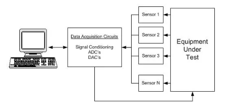
Figure 5:Data Acquisitions Block Diagram
The block diagram up top shows how the device is observed's data is being collected. The appliance is equipped with a variety of sensors. These sensors are connected to a computer through DAQ. DAQ places an order for the circuit upgrade. This improves the device's quality and function after being checked. The underground wire fault tracker's effectiveness may also be enhanced by it. When the DAQ circuit and alarm system are connected to the microcontroller, the alarm system may instantly identify the problem while also displaying the defect's location on the screen. It will boost the system's efficiency and dependability.

Figure 6: DAQ using 8051 microcontroller
The schematic for a DAQ system employing an 8051 microcontroller was displayed on the preceding page. All the required tools are displayed in the diagram. A system should be equipped with all of the necessary components to increase its efficiency. It will be simple for the device to obtain data if the microcontroller is connected to the DAQ circuit. Any programme should include a human interface. To increase the effectiveness of the computer, people should interact with it properly. The other devices can only be linked using the user interface. In order to increase application efficiency, a network's necessary devices should all be connected.
References

Thesis Writing
Wind Turbine Power Production Estimation for Better Financial Agreements Assignment Sample
CHAPTER 1
INTRODUCTION
One of the energy sources with the quickest growth both domestically and internationally is wind energy. The installed capacity of wind turbines in the United States has expanded over the last ten years from 40.18 GW to 113.43 GW, and is expected to reach 224.07 GW by 2030 [1]. Traditional power purchase agreements have become less prevalent as the number of wind energy projects has increased. Therefore, financial arrangements have been used by wind farms to ensure their revenue stream. The idea of proxy generation (PG), which is used to calculate the potential power output of wind farms under ideal circumstances, is one of the key elements of these financial arrangements. Understanding the links between the production of a wind project and the related financial arrangement, and therefore the revenue and risk of the project, is crucial for maintaining the development of wind energy.
Traditionally, power purchase agreements—which provide a fixed price for each kWh produced—were used to finance wind energy projects. As a result, the project's anticipated performance is totally dependent on the estimated yearly energy production (AEP). The cost of power can vary greatly, particularly on a daily and annual basis. Wind-independent electricity costs are subject to large seasonal and on-peak price fluctuations [2]. Power Purchase Agreements (PPAs) insulate the development of wind energy from these variations. Financial agreements like the virtual PPA and proxy revenue swap have evolved as practical alternatives to PPAs, which are becoming less common (more on this in section 2.2.1). (discussed further in section 2.2.2). Using proxy generation, which is the calculation of the wind farm's expected output based on a
These agreements minimize risk to both parties and stabilize cash flow since they estimate wind farm power generation in light of weather conditions [3].
Wind power plants may be subject to significant price risk when exceptional price occurrences take place and coincide with a significant estimation inaccuracy for the power generated by wind turbines. The price swings that took place in Texas in February 2021 are an excellent illustration of the conditions that can trigger these pricing occurrences. The financial performance of wind farms may be affected differently by various proxy generation calculation techniques. Financial agreements with a more favorable risk balance for both parties will result from a better knowledge of the techniques for estimating proxy generation and the accompanying prediction errors, as well as how PG corresponds with electricity pricing [4]. In order to better educate financial models that rely on proxy generation, this thesis compares two power prediction methodology and their results in relation to price.
The objectives of this thesis are to deepen our understanding of how various power prediction techniques affect wind farm financial performance.
• To calculate proxy generation, create and validate a Nacelle Transfer Function (NTF) model in Python.
• Create and test a Python Reanalysis Data model for the production of proxies.
• Compare the outcomes of the two strategies for proxy generation and revenue.
Background information on estimated wind turbine power production and financial arrangements for wind farms is provided in Chapter 2. Chapter 3 provides details on the wind farm and associated utilized data sets for this analysis. The NTF and Reanalysis Data techniques are covered in Chapters 4 and 5, respectively. In Chapter 5, the outcomes of the two approaches are contrasted. The analysis is summarized in Chapter 6 along with suggestions for additional research.
CHAPTER 2
BACKGROUND
2.1 Wind Turbine Power Production
The power curve is used to describe how much power is produced by wind turbines (discussed further in section 2.1.1). An estimation of the annual wind energy production by the farm is produced by fusing the power curve with the wind speed distribution at the site (explained further in section 2.1.2). This generation estimate serves as the foundation for the revenue estimation utilized in financial agreements, together with a pricing estimate. Below is a list of the elements that go into producing wind energy, along with information on their challenges and potential solutions.
2.1.1 Power Curve
The electrical output of a wind turbine is related to the inflow conditions by the wind turbine power curve. These are produced by companies that make wind turbines, and they are typically based on test data and specifications from the IEC 61400-12-1:2017 [1]. The International Electro technical Commission (IEC) is in charge of upholding the set of design specifications to ensure that wind turbines are constructed securely and in accordance with particular technical standards.
Figure 1 below is an illustration of a power curve and highlights key areas.
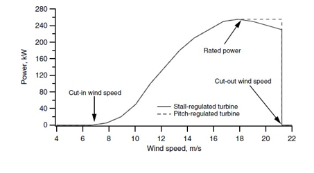
Figure 1: Wind turbine power curve [2]
Power curves are influenced by a wide range of variables, and the reference power curve might only be applicable to specific climatic or topographic regions. Power generation deviates from the values anticipated by a manufacturer's reference power curve, according to extensive research on power curve accuracy and the effects of complicated wind regimes on turbine performance [3,[4,[5]]. However, a novel idea is to examine the variation between proxy and actual generation.
Additionally, turbulence severity, wind shear, and terrain can cause deviations in power curves [3], [4]. Additionally, estimating the vertical wind speed and shear profile using the standard power law equations can be erroneous due to various meteorological events, such as the Low-Level Jet that occurs in the Great Plains/Midwest region [5]. Additionally complicating wind conditions are terrain and wake effects.
These same factors are anticipated to have an effect on the findings because this research will use manufacturer sales power curves. But in the context of monetary settlements,
Turbine performance is said to be influenced by deviations from the warranty (reference) power curve, which is also referred to as operational risk and partially accounted for in predicted operating losses (discussed further in Section 2.2).
2.1.1 Wind Speed Characterization and Measurement
As shown in Figure 2, of this Engineering assignments the wind speed at a location varies with time, and the Weibull distribution is frequently used to describe the long-term wind speed probability distribution. A time series of the site's measured wind speed is constructed to create this distribution. The two most common time series to employ are those with 10-minute average wind speeds and 1-hour average wind speeds. A probability distribution, such as the Weibull, can then be used to fit a histogram of the recorded wind speed.
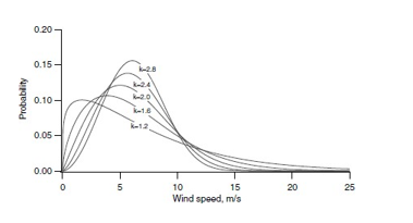
Figure 2: Weibull probability density function for U =6 m/s [2]
Scale and shape are the two parameters that make up the Weibull distribution. The distribution's mean and shape are determined by these characteristics.
The estimated energy output of a wind turbine is typically determined by integrating the product of the turbine power curve and the probability distribution of wind speed across all wind speeds. This results in a long-term forecast of the anticipated yearly(AEP) does not take into account seasonal fluctuations in wind speed. In other words, the amount of energy generated during any given season may be very different from what would be expected based on the long-term wind speed probability distribution [4]. There are variations that take place on shorter time frames in addition to seasonal variations.
Several methods, including a nacelle anemometer, a meteorological mast (met mast), or remote sensing equipment, can be used to measure and gather wind speed data. A combination of observations and models can also be used to estimate wind condition data, as is the case with MERRA (Modern Era-Retrospective Analysis for Research and Applications) (discussed further in Section 3). This study will look at proxy generation trends based on these many sources of wind speed data. An estimation of the wind speed without the rotor, which contains uncertainties, is necessary for nacelle anemometer wind speeds, which are obtained from anemometers positioned on the turbine nacelle's back. Met mast wind speeds originate from towers that are not necessarily near the turbines and, as a result of the impacts of the terrain, may have values that are different from the actual wind speed that a turbine experiences.
The use of MERRA reanalysis data, which are a synthesis of global wind observation data, is very recent for this application [6]. In addition to the previously mentioned uncertainty in data sources, wake effects from turbine-turbine interactions also contribute to the variability in wind speed readings. The accuracy of the proxy generation calculation will be examined in this analysis in relation to the effects of these various sources of wind speed.
2.1.3 Proxy Generation (PG)
Proxy generation is a production estimate that is based on idealised inflow circumstances. The following section [7] describes proxy generation.
NTF is the nacelle transfer function, and WSnacelle is the nacelle wind speed. PowerCurvewarranty is the power curve for the warranty (reference), and
Power performance losses, wake losses, lockage losses, and transmission losses inside the plant are all included in ExpectedOperationalLosses. The NTF ratio converts the nacelle wind speed to "free stream," and the corrected wind speed is utilised with the power curve to calculate energy. Both the NTF and the Power Curve are non-linear wind functions.
Even while it has only focused on performance in flat terrain, some study has started to look at the mistake in proxy creation [7]. With good measurement control, it has been demonstrated that the uncertainties from NTFs can range from 4 to 8%.
The final PG result is influenced by a wide range of distinct factors, each of which has the potential for mistake. The measurement of wind data is uncertain. Other potential causes include broken or malfunctioning equipment, improperly installed nacelle anemometers, and misaligned turbine controller settings. Project Met mast turbine pair data is used to construct the nacelle transfer function, which is subsequently applied to additional wind farm turbines without taking wake effects into consideration. Inflow angle, turbulence intensity, and mounting of the measuring arrangement are all important factors. The contract power curve from the manufacturer is the power curve employed in this equation, and the actual
Production will also differ (as discussed in section 2.1.1). Site calibration concerns exist in the projected operational losses, and proxy generation is known to understate these values [4]. The final proxy generation computation, which will be compared to the actual generated power, is affected by all of these causes of error.
2.2 Wind Energy Financial Models and Agreements
Since the beginning of the sector, wind energy finance models have undergone tremendous change, and current agreements are also undergoing modification [8]. Wind farms would sell their products directly into the electricity market if no financial arrangement were made. Since wind projects require stable revenue to be profitable, the emergence of standard PPAs was a response to the merchant structure's fluctuating cash flow effects. PPAs are continue to be phased out and replaced by swaps, hedges, and virtual power purchase agreements as a result of the lack of purchasers driving PPA costs low (discussed further in section 2.2.2 and section 2.2.3). The goal of our work on proxy generation is to enable financially sound agreements as the sector expands.
2.2.1 Power Purchase Agreements
Traditional PPAs are long-term, fixed-price agreements, often between a wind project and a utility or end customer of electricity, that last for 15-20 years [9]. There is a small pool of consumers (utilities and end users), but there are lots of producers (developers of wind projects), hence the costs for these kinds of agreements are low. As seen in Figure 3, fewer traditional PPAs are being created as a result of pricing and a dearth of purchasers. When wind projects are compelled to seek out alternate arrangements, the number of synthetic PPAs rises [10].
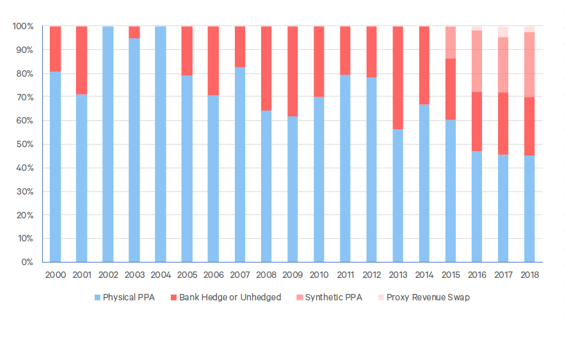
Figure 3: Since 2000, the amount of US wind capacity installed has been broken down into physical PPA or commercial structures [11].
With regard to the erratic and unpredictable nature of the wind, this financial structure is made simpler by charging a fixed fee per kilowatt hour in a PPA [12]. This, however, pushes wind projects to sell electricity at a lower, guaranteed price, which may result in less profit. Because typical PPAs are becoming less expensive, the industry is shifting toward alternative contracts that aim to take into account the intricacies of wind speed variability, boost revenue, and still safeguard wind projects from changes in energy prices [11].
2.2.2 Financial Hedging and Strategies
Cash flows for wind energy projects have been able to be stabilized through the use of financial agreements like hedges and virtual PPAs. According to their name, virtual PPAs never actually involve an exchange of electrons between the counterparty and the wind farm. Rather, both of the
Direct wholesale market transactions between a wind farm and counterparty result in a settlement between the two parties equal to the difference between the market and pre-set fixed price. Renewable Energy Credits (RECs) for the counterparty may also be an advantage of virtual PPAs [13]. In a bank hedging agreement, the wind farm commits to producing a specific amount of electricity, but the settlement sum varies according on the energy market price.
The payment arrangement for a virtual PPA between the hedge provider (company), electricity market (power pool and utility), and wind project (renewable energy system) is shown in Figure 4 below.
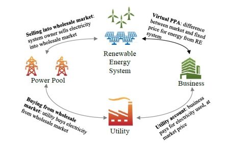
Figure 4 shows examples of digital PPA transactions [10]
The Actual Generated Quantity (AGQ) is frequently utilised in virtual PPAs to establish the fixed price of energy [7]. The AGQ represents how much energy the project actually produces. The hedge provider may experience problems if AGQ is used to settle price.
when the amount created is not what was anticipated. Operational risk resulting from clashing interests between the hedge provider and the wind farm is one element that could be problematic [14]. The counterparty wants to have no exposure to operational risk because AGQ is partially reliant on how well the wind farm is operated and maintained. The operational risk is eliminated for the hedge provider by using Proxy Generation (PG) as opposed to AGQ, which is based on measurable input rather than measured output [15]. Given a set of weather circumstances, PG estimates the amount of energy that the wind farm should produce, placing the operational risk on the wind farm, which is the entity in charge of the operation.
No matter how much electricity is produced, the wind farm is still liable for paying the settlement sum for bank hedges. Wind is a variable resource, yet a fixed amount of electricity must be delivered regardless, hence the wind project must assume the risk associated with the weather. This is lessened by proxy generation, which permits projected energy production to vary in accordance with the measured availability of the wind resource.
2.2.3 Financial Settlements with PG
In order to strengthen financial agreements for both sides, the accuracy of proxy generation will be increased. This will give hedging providers and wind farms a clearer idea of what the project should have produced. There is therefore a chance that wind readings will affect project revenue. Through two major financial settlements—the Proxy Generation virtual PPA (PG-vPPA) and the Proxy Revenue Swap—PG is now responsible for the financial health of wind project (PRS). Similar to virtual PPAs, PG-vPPAs function.
Regardless of the amount of energy used or the cost of electricity, PRS have a predetermined lump sum. This amount serves as a standard; if proxy revenue surpasses benchmark (lower than anticipated wind speeds or prices), project pays counterparty; if proxy revenue falls short of benchmark (lower than expected wind speeds or prices), counterparty pays project [16].
The advantage of PG is that it decouples operational risk from the counterparty [11], [7], allowing the party in charge of operations (the wind farm) to manage operational risk. As a result of the agreement's structure and flexibility in that it does not require a set amount of power to be produced, the wind farm is encouraged to run at maximum efficiency [11]. As the wind farm is no longer required to provide a specific amount of power, PG in the financial settlement also permits freedom on their part. The counterparty is in charge of weather risk, which is reduced by using PG-based financial agreements because they are better equipped to handle these weather variations [17]. Unlike earlier virtual PPAs and hedge agreements, these contracts provide protection for both parties.
When wind and price are unfavourably connected, there are some price concerns involved with employing PG estimations. As can be observed in Figure 5, ERCOT South exhibits a sharp increase in hub pricing at low generation levels, which are indicative of low wind speed. Due to the correlation between pricing and PG error, it is crucial to not only reduce total PG error but also comprehend underlying trends, particularly at interest wind speeds.
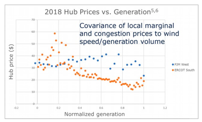
Figure 5: Hub Prices vs. Generation [7]
Figure 5 shows an instance that happened on a hot summer day in Texas when there was little wind and there was a huge demand for energy because of the massive power that A/C units used. The 10–12 February 2021 Texas hurricane was another startlingly expensive energy event, with the cost of energy reaching $9,000/MWh. The wind farm is still liable for the settlement if there is a sizable difference between proxy and actual generation during these pricing events. As a result, the financial performance of the wind farm may be significantly impacted by various proxy generation calculation techniques, which will be discussed more in Section 6.
CHAPTER 3
SITE OVERVIEW
3.1 Site Overview
North Texas is the location of the wind farm that was examined for this research, and Figure 3-1 depicts its layout. With a wintertime northerly component, the winds are primarily from the south. Take note of the 4 triangles designating met masts:

Figure 6: Turbine layout at project
3.2 Dataset
3.2.1 Turbine SCADA data
For all turbines from December 1, 2017, to November 30, 2018, 10-minute intervals of turbine SCADA data are supplied. This dataset includes the following variables: turbine power, nacelle wind speed, rotor position, operating status, temperature, and density corrected nacelle wind speed. A turbine OEM-applied nacelle transfer function, which is not site-specific, is used instead of a nacelle anemometer's raw wind speed data. The NTF approach enables the application of a further, site-specific NTF (discussed further in chapter 4).
3.2.2 Mast data
Three permanent and one temporary met masts were installed at the location. Masts 9710–9712 contain data from the SCADA system, while mast 9713 contains non–SCADA data from the Campbell Scientific data logger. The fourth one wasn't used in this investigation, and only three of them are linked with test turbines.
3.2.3 MERRA-2 Reanalysis data
The NASA Global Modeling and Assimilation Office's long-term global reanalysis effort is the Modern-Era Retrospective analysis for Research and Applications, Version 2 (MERRA-2) dataset. In the latitudinal direction, the spatial resolution is around 50 km. Data on the wind state are provided every hour at heights of 10 m and 50 m.
3.2.4 ERCOT Price data
The Electric Reliability Council of Texas (ERCOT) HB West hub provided the price dataset for this investigation in 15-minute intervals. During the analysis period, the highest price per MWh was $1406.43, and the lowest was -$18.40.
3.3 Data Filtering and Analysis
Filtering the raw data from the turbine and mast data was the initial phase, followed by building the framework to produce proxy generation figures. Python was used to complete this.
The following are the steps for data filtering:
1. Using the pairings in Table 2, combine the turbine and mast data using timestamps.
2. Determine the air density for every 10-minute data point. Due to the area's flat geography, a single density dataset that was based on data averaged between Masts 9710 and 9711 was used for the project. The following equation can be used to determine air density (taken from IEC 61400-12-2 9.1.1 Eq 4):
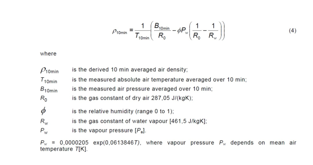
3. Determine the power curve's turbulence class (medium). For details, refer to the Appendix.
4.) Change the ERCOT pricing database's intervals from 15 to 10. For information, see Table 1.

CHAPTER 4
NACELLE TRANSFER FUNCTION (NTF) METHOD
4.1 Model Development
The NTF method determines the power production for each individual turbine by using measurements taken on-site from met masts and anemometers mounted on turbine nacelles. This data is then added together to determine the proxy generating value for the entire site. In order to account for the influence of the terrain on the wind speed measurement, this site-specific NTF offers an additional adjustment to the nacelle wind speed. These NTFs are created using Python programmes from met mast and turbine pair data. Following is a diagram of the turbine/mast coupling in Table 2:
Table 2: Mast/Turbine Coupling
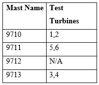
The NTF approach involves the following procedures for generating proxy generation and proxy revenue values:
1. For valid data, compute Nacelle Transfer Functions (NTF). In this instance, the nacelle anemometer wind speed (NWS) and front-of-rotor, or "free stream," wind speed are related via a reference table (NTF), with the met mast serving as free stream. Data from a time period with both valid met mast and NWS accessible was chosen, and it was processed in accordance with the requirements of IEC Standard 61400-12-2. Utilizing only information from unrestricted direction sectors, subject to the restrictions listed in Appendix E. The data were divided into 0.5 m/s bins, and the ratio between the met mast and the NWS was determined for each bin [18]. Each mast/turbine pair's data was used to construct an NTF. These offer a conversion ratio to translate the wind speed observed at the test turbine's nacelle into the wind speed reported at the corresponding met mast. Table 2 provides a list of mast/turbine couples. There are seven NTFs in total, including the six mast/turbine pair NTFs and a site-wide NTF that uses the data from all mast/turbine pair NTFs averaged together. Seven different PG results are computed using them, and they will be contrasted in section 4.3.
The full NTFs are included in Table 3 along with an example NTF. The average wind speed for all wind speeds between 2.25 and 2.75 is contained in wind speed bin 2.5. The average wind speed at the met mast is known as Met Mast, while the average wind speed at the nacelle is known as NWS.
Table 3: NTF for Turbine 1
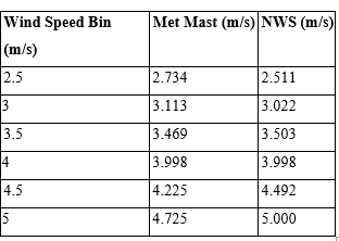
2. Utilizing linear interpolation, apply NTF to all reliable nacelle wind speeds from every turbine at the location. The following equation is employed (taken from IEC 61400-12-2 D.4 Eq D.1 [19]):
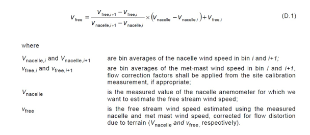
3. Adjust the free stream wind speed to the contract power curve's reference air density. The formula is as follows. (from IEC 61400-12-29.1.1 Eq 6):
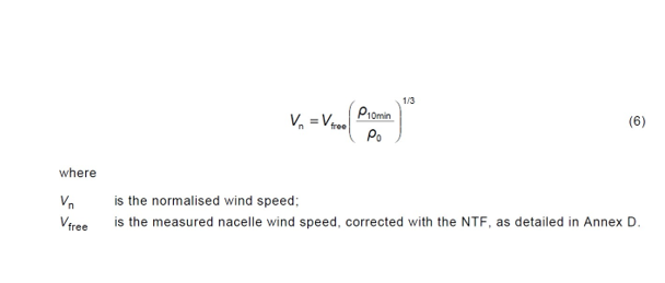
4. Use linear interpolation to determine proxy generation by applying the power curve to normalized free stream wind speed. Now we'll have a proxy value of each turbine's generation. For further information on power curves, see Appendix A.
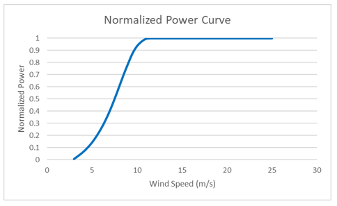
Figure 7: Manufacturer power curve
5. Sum turbine output at each time stamp to generate proxies over the entire site
6. Evaluate proxy generation revenue using price information:
???????????????????? ???????????????????????????? = ???????????????????????????????????????? (?????????) ∗ ???????????????????? ($ /?????????)
7. Repetition of steps 2 -6 with the remaining NTFs. There will be a set of PG results for each NTF, for a total of seven sets.
8. To analyze the effects of the site-specific correction, steps 3-6 are finished using the nacelle wind speed rather than the corrected free stream.
4.2 NTF Method Validation
The created NTFs were then compared to earlier research. Overall, the values appear to be consistent, demonstrating the validity of the methodologies employed here and the suitability of the NTF model for further investigation.
4.3 Error in NTF model
The NTF model depends on onsite measurements, which are costly, require upkeep, and require calibration. To accurately capture the front-of-rotor "free stream" to nacelle anemometer wind speed relationship, it is difficult to determine how many mast/turbine pairs are required. It was feasible to assess the potential range of results if various configurations were implemented by comparing the proxy generation results from all mast/turbine pairs. The nacelle anemometer wind speeds were employed in the calculation of an additional nacelle wind speed (NWS) proxy generation result without the addition of an NTF ratio. Analyzing the effects of on-site measurements and site-specific NTFs was possible. Results from six distinct test turbine NTFs, as well as a comparison with the NWS and site-wide NTF, are shown in
Figure 8. One is the slope of the red dashed line.
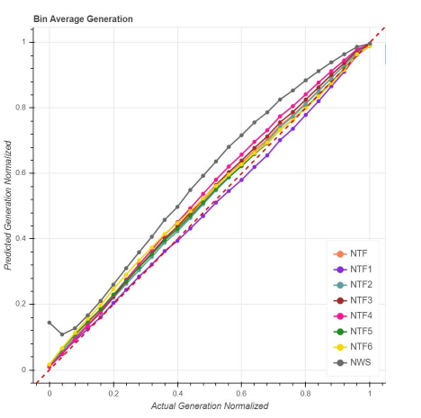
Figure 8: Bin Average Generation for all NTFs
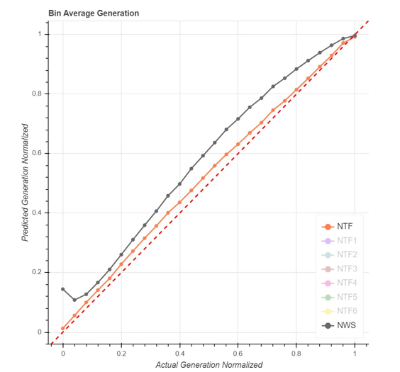
Figure 9: Bin Average Generation for site wide NTF and NWS
The distinction between the site-wide NTF and the NWS findings' bin average generation is depicted in Figure 9 above. The annualised proxy generation calculations in Table 4 reflect that the NWS results overpredict generation by a significant margin compared to the site-wide NTF. The influence of the site-specific NTF is clearly shown by this chart.
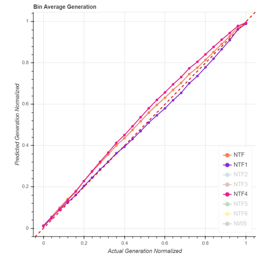
Figure 10: Bin Average Generation NTF method range
Along with the biggest and smallest NTF mast-turbine pair generating estimations, Figure 10 displays the site-wide NTF data. This illustrates the "working envelope" of the various mast-turbine pairs as well as the variety of possible outcomes in scenarios where there are less mast-turbine pairs at the location. Varying mast/turbine combinations will produce different NTF ratios as a result of the terrain's variation, which ultimately affects the wind project's financial performance.
The findings for the same mast and various turbine sets are shown in Figures 11 and 12 below. The largest variation between this type of pair is seen in Figure 11, illustrating how even with the same met tower, topography influences and other turbine variations may have an impact on NTF generation.
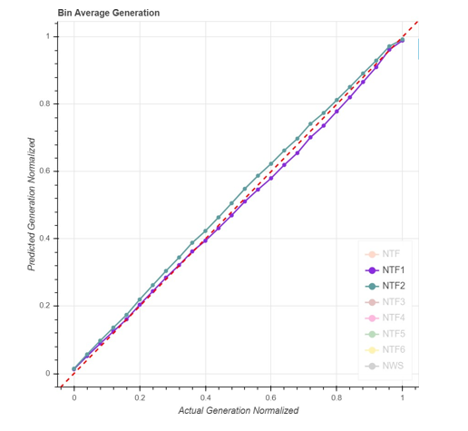
Figure 11: Bin Average Generation mast/turbine pair comparison 1
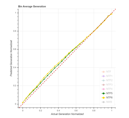
Figure 12: Bin Average Generation mast/turbine pair comparison 2
The outcomes of the NTF method's proxy production and revenue are shown in Tables 4 and 5. The site-wide average for the NTF comparison for proxy generation falls about in the middle of the range of errors, which vary from a 3% underestimate to a 10% underestimate. The range of the proxy revenue results is between a 9% and a 1% underestimation.
Compared to the outcomes with a site-specific NTF, the NWS model greatly overestimates both generation at 2% and revenue at 7%. This outcome illustrates how the site-specific NTF affects the precision of the production estimate. The nacelle anemometer and turbine OEM applied NTF do a poor job of capturing the impacts of terrain on wind speed.
Table 4: NTF Proxy Generation
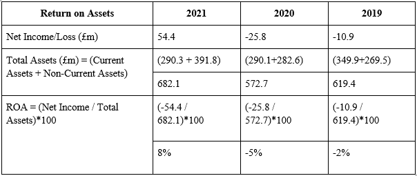
Table 5: NTF Proxy Revenue
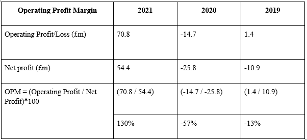
With the goal of investigating the effects of terrain and met mast distance on the accuracy of the PG estimate, Figure 13 below shows the distance between the test turbine/met mast with the error in PG and Proxy Revenue (PR). Given that the site's landscape consists of of flat farmland, it appeared logical that the discrepancies in the PG results would be more affected by the distance to the met mast. There isn't a clear causal link between the two, though, according to these findings.
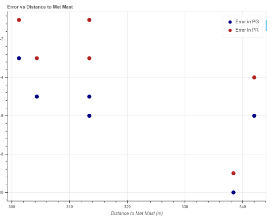
Figure 13: Distance to Met Mast vs Error
CHAPTER 5
REANALYSIS DATA METHOD
5.1 Model Development
The Reanalysis Data technique forecasts site-wide power production using a single wind speed and direction pair derived from the MERRA-2 database. In the absence of turbine SCADA or other site measurements, the financial agreement may be established by calculating proxy generation using reanalysis data.
A power matrix—a lookup table of wind speed and wind direction that calculates site-wide power—is generated using measured data from the turbine and mast. The met masts were used to establish wind speed and direction binning for the power matrix in order to take array and obstruction effects into account.
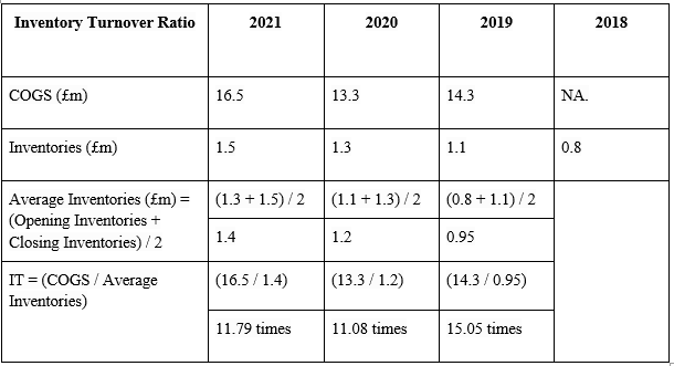
Table 6: Power Matrix Valid Sector Designations
The following are the stages to creating the power matrix:
1.) In order to calculate site-wide power, the power from each individual turbine was added at each timestamp where availability was more than 90%, and the associated met mast wind speed and direction were used.
2. To build the power matrix, the power was averaged over wind speed and wind direction. These manual edits were made:
a.) Based on the warranty power curve, power was taken to be zero at wind speeds below cut in.
b.) Unfilled bins were filled with the average site-wide rated power at wind speeds above the rated power up to the cutout wind speed.
Find the power matrix in Appendix D.
The following are the steps to generate proxy generation and proxy revenue figures using Python scripts and the Reanalysis Data method:
1.) From the database, MERRA-2 data for the nine grid locations closest to the wind farm were obtained. This investigation focused on the four closest to the project, denoted below by the letters W, C, SW, and S.
2.) To calculate hub height wind speed, a wind shear extrapolation model is utilised in conjunction with MERRA-10 m and MERRA-50 m wind speed information. The formula is as follows:
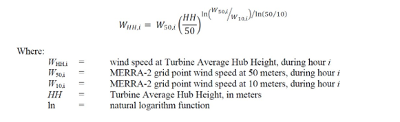
3.) To calculate the estimated project wind speed, four nearby MERRA-2 hub height wind speed sites are used (EPWS). Here is the equation that is used:
.png)
4.) The following equation normalises the EPWS to the site air density. (from IEC 12-2 9.1.1 Eq 6):
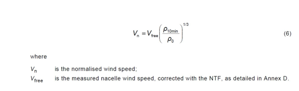
After that, using the wind speed information gathered at the met mast in the legal
sector, the normalised EPWS is rectified:
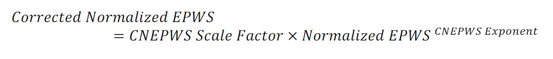
By fitting MERRA and each sites met mast wind speed exponentially, the CNEPWS Scale Factor and CNEPWS Exponent were determined. The exponents and scale factor from each of these were averaged. Results for the scale factor and exponent are shown in Table 7 below.
Table 7: CNEPWS Scale Factor and Exponent
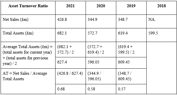
As a weighted average of the wind vectors for each of the MERRA-2 grid points, the 50 m project wind direction was derived. Each wind vector's weight was determined by the inverse-square distance between the corresponding MERRA-2 grid points and the project site's geographic centre.
7.) The MERRA corrected hub height wind speed and the MERRA-50 m project wind direction are both subjected to the power matrix. The wind direction and wind speed at each timestamp were determined by linear interpolation to be closest to the value in the power matrix.
a. Error in reanalysis (MERRA-2) model
Three elements needed to be analysed to determine the MERRA-2 technique error:
1. Direct parameter comparison between onsite measurements and MERRA-2.
2. A comparison of proxy generation to look at flaws in the power matrix and outcomes after transformation through turbines.
3. A comparison of proxy revenue is used to assess the financial effects of the power matrix approach and any potential PG error amplification.
Figure 14 below is a scatter plot of MERRA-2 against wind speeds recorded at Met9711. It begins with the direct parameter comparison of onsite measurements vs. MERRA-2. Despite being site adjusted, it is evident that MERRA-2 estimations already have substantial differences from the site's real wind speeds (step 5 in Section 5.1). The comparisons between proxy revenue and proxy creation are covered in Chapter 6.
.png)
Figure 14: MERRA-2 vs Met 9711 Wind Speeds
CHAPTER 6
MODEL COMPARISONS
6.1 Proxy Generation and Revenue comparisons
The results of both the NTF method and the MERRA-2 method came from time series data collected from January 2018 to September 2018. By comparing results from the same time period, you can look at the financial effects of each estimate of power production during that time.
In Figure 15, you can see how real generation compares to MERRA-2 and the NTF method. It's clear right away that the NTF method is much closer to how generation really works. The NTF method has a much smaller error spread and a lower risk of a single event. The most important things are big differences between the proxy generation and the real generation, especially if they happen at the same time as a big price change. This is a lot more likely to happen with MERRA than with NTF.
Figure 16 shows how real income compares to MERRA-2 and the NTF method. The MERRA results show that errors are much more spread out, especially when revenues are higher.
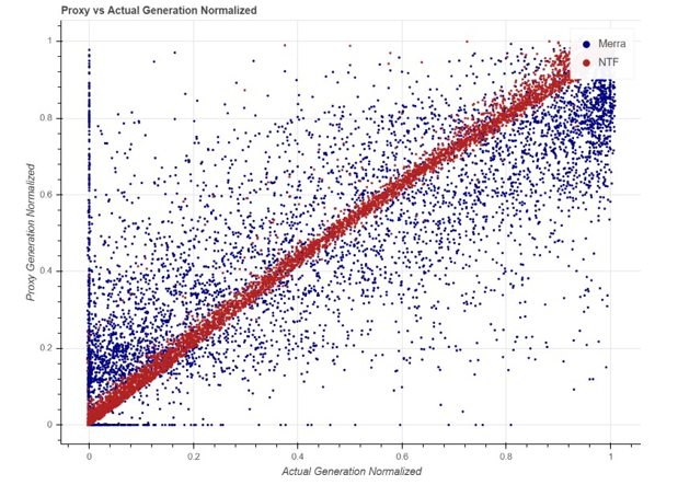
Figure 15: Proxy vs Actual Generation Scatter
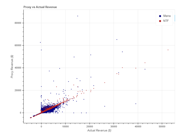
Figure 16: Proxy vs Actual Revenue Scatter
Error in generation and income are shown as a time series in Figure 17. Here, Error in Generation shows the same patterns as Figure 15. The error spread for MERRA is a lot bigger than that for NTF. When the error is big and the price of electricity is high, events tend to stand out more in the revenue time series.
During the time we looked into, there were two times that stood out. From March 8 to 10 and July 19 to 26, 2018, the error in MERRA-2 is always big, while the error in the NTF method is close to zero. After more research, it was found that none of the turbines at the site were working normally at these times. It is likely that the turbines were turned off for maintenance at these times. Taking these times out of the dataset didn't change the final results much, so they were kept.

Figure 17: Proxy – Actual Generation and Revenue Timeseries
Figure 18's two histograms are incorrect. No such source was found. Show the two approaches' different error spreads once more, highlighting how the MERRA-2 method's error range is substantially wider than the NTF method's.
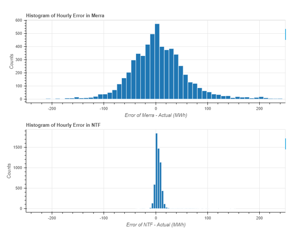
Figure 18: Error in PG Histogram
Below is an overview of statistics in Table 8. The mean error of 5.15 MWh is not yet representative, and the true value is slightly less because the operational efficiency losses have not yet been taken into account by the NTF technique in this case. Despite the fact that MERRA-2 mean error
It is evident from both the histograms and accompanying standard deviations that the error of the NTF method is much lower and is only marginally higher than that of the NTF approach.
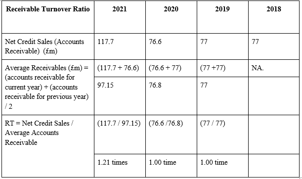
Table 8: Summary Statics for Error in PG
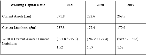
Table 9: Summary Statics for Error in PR
The annualised generation and revenue of the two approaches are contrasted with the actual amounts in Table 10 below. The MERRA approach only has a mean error of 5% when generating proxies, but since the method overestimates project revenue by 7%, the proxy revenue demonstrates that the inaccuracy in generating proxies was poorly timed with the price of energy. In comparison, the NTF technique underpredicts project revenue by just 3% and its prediction diminishes from generation to revenue.
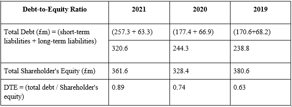
Table 10: PG and Actual Generation and Revenue Comparison
The annualized findings show that the percent error in PG for MERRA is in the same ballpark as the results from the NTF approach. However, shorter time frames need to be examined for the effects of a price excursion, which are further explored in the section below.
6.2 Time duration analysis
If the duration of these approaches is substantial, the error will probably have a greater effect. The settlement computation is unaffected if the model makes some over predictions and some under predictions, but evens out to zero error over the period of an hour. A price excursion event could occur and have an impact on the outcomes if the model "evens out" the inaccuracy over the course of several hours or days. As a result, we looked at how long it would take for the error to become equal.
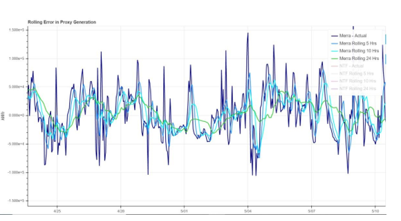
Figure 19: MERRA-2 Rolling Avg Error Generation
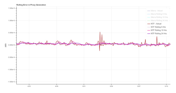
Figure 20: NTF Rolling Average Error Generation
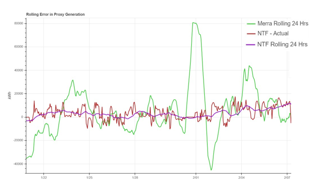
Figure 21: NTF vs MERRA Rolling Average Error in Generation
On a rolling average of 1, 5, 10, and 24 hours, Figures 19 and 20 above display the MERRA-2 and NTF error in generation, respectively. The NTF technique is balanced by rolling error significantly.
Even with a 24-hour rolling average, MERRA-2 still exhibits a significant magnitude of inaccuracy.
Comparing the NTF hourly and rolling average 24 hours to the MERRA-2 rolling average 24 hours is shown in Figure 21. The level of error between the two strategies differs significantly. For instance, a wind farm using the reanalysis method for their settlement would have to pay a much higher settlement than one using the NTF method if the significant green spike that appears in the MERRA-2 result at 01 February had actually occurred in Texas between February 10 and 12, 2021, when the price of energy was $9000 MWh. The primary focus of this work is on this kind of price excursion that correlates with significant errors in energy estimations. It is obvious that the NTF technique outperforms the MERRA-2 reanalysis method in proxy generation calculations by offering reduced price risk.
The rolling average errors in wind speed and proxy generation are shown in Figures 22 and 23, which provide additional analysis in the MERRA-2 approach to identify the error. On an hourly time scale, the MERRA-2 wind speed error is much worse than the onsite observations (see section 5.2), however when looking at the rolling average error up to 24 hours, it significantly decreases. As MERRA-2 is known to be less accurate at finer temporal scales, this is not surprising.
The same trends, however, are not visible when looking at the MERRA-2 proxy generation's rolling average error. Figure 23 displays the rolling error in PG over various longer time periods up to one month, and the MERRA-2 values still have a wider range and more uneven distribution of error than the NTF approach. This suggests that a significant portion of the reanalysis data method's errors come from the power matrix.
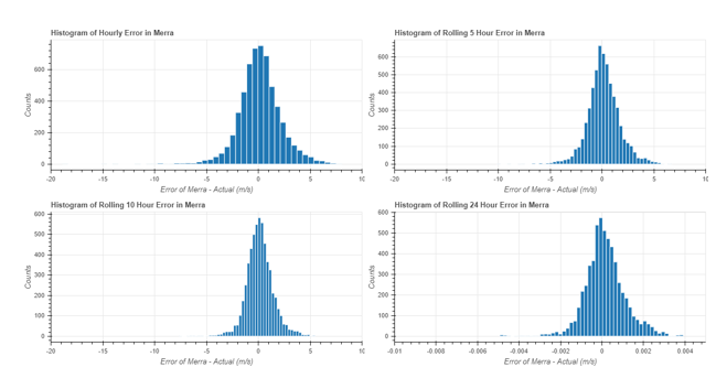
Figure 22: MERRA-2 Wind Speed Rolling Average Histograms
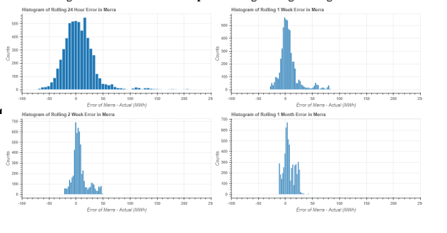
Figure 23: MERRA-2 PG Rolling Average Histograms
An error matrix for MERRA-2 is shown in Figure 24 below. This investigation was done to see if there were any parts of the power matrix that were primarily to blame for the MERRA-2 error. Instead, all of the places with significant inaccuracy were concentrated near where the majority of the information was. Additionally, cells with large over- and underestimates were all situated close to one another. Future research should focus on this because it appears to show that the error is rather random (discussed further in Section 7.2.1).

Figure 24: MERRA-2 Error Matrix
CHAPTER 7
CONCLUSIONS AND FUTURE WORK
7.1 Concluding Remarks
The mast/turbine pair configuration at the site is proven to affect the NTF method results, which eventually affects the project proxy revenue. One of the risk factors in the NTF technique is the number of met masts and mast/turbine pairings at the site. In comparison to using only the nacelle wind speed with the OEM corrected NTF, using met masts and a site-specific NTF considerably improves the accuracy of both wind turbine power forecast and proxy revenue. The results of this case study demonstrate that the reanalysis data method, which attempts to estimate the site-wide proxy generation using a single wind direction and wind speed, is a subpar estimation technique.
Overall, employing local wind condition observations for turbine power prediction has significant advantages. The NTF approach manages price excursion risk significantly better than MERRA-2. The unfavorable association between wind and pricing was one of the initial driving forces behind this initiative. The events in Texas in February 2021 were an extreme example illustrating a conceivable scenario in which various power projection systems may have a significant impact on the financial settlement for a wind farm [20].
The financial settlement may be determined using proxy generation results from MERRA-2 data if turbine SCADA or other on-site measurements are not available.
The cost repercussions of that decision are demonstrated by contrasting the NTF technique and MERRA-2 results. The wind farm may experience serious financial consequences if a severe price event coincides with a financial settlement determined using MERRA-2.
7.2.2 Additional projects
This case study was performed on a wind site in north Texas, with relatively simple terrain. This analysis should be performed on data from other wind projects, as well as those in more complex terrain. Financial settlements using the PG values from both NTF and reanalysis data methods are already in place without an understanding of the financial implication of either method. Better understanding of the impacts of each method across varied terrain should be explored.
7.2.3 Applications in other agreements
Other uses for the creation of two distinct models to forecast site-wide electricity generation exist in addition to wind farm financial agreements. Now, settlement and curtailment agreements as well as contractual guarantees can be analysed using the methodologies developed here.
REFERENCES
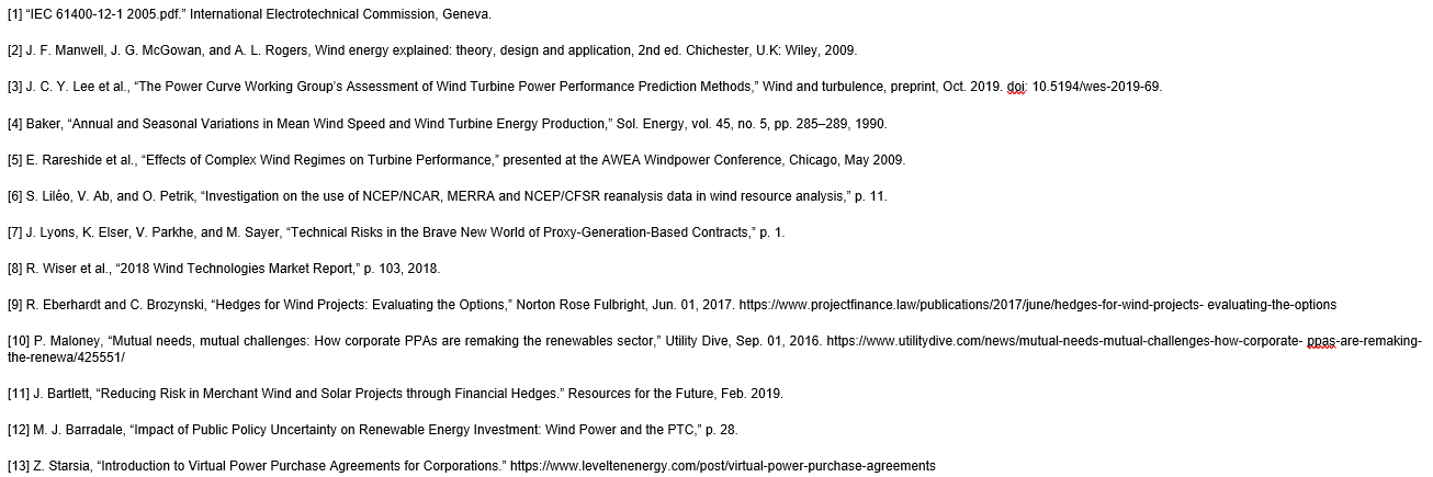

Research
SENG205 Software Engineering Assignment Sample
Length/Duration: 1000 Words (+/- 10%)
Unit Learning Outcomes addressed:
1) Describe compare and contrast various methodologies for software development processes
5) Be able to select an appropriate development method for a complex problem and give technical reasons for the choice
6) Be able to gather requirements, develop specifications, design, implement and test a prototype individually and in a team.
Submission Date: Week 5
Assessment Task: Initial Design – the plan and its justification
Total Mark: 15 marks
Weighting: 15 % of the units’ total marks
Assessment Description for Assignment Help
Assessment 2 will be an initial design of your project – showing your project plan and its justification. You need to write 1000 words summary on initial project information, elicit high level requirements, classify and prioritize the high level requirements, choose a software development methodology and justify its choice, initial project timeline, and preliminary budget breakdown. You need to work in groups of 4-5 students. Further details of assignment is provided on the Moodle site in “Project Outline” Document in Assessment Briefs folder. The students contribution and performance towards preparing the report will be accessed via peer review document.
Solution
Introduction
A person's education is an important factor of their life; depending on their career, it will either make or break them. Today's education is far more diverse than it was in the 1950s thanks to advancements in teaching approaches and other significant inventions that use more overt teaching methods(Hitka et al., 2021). In e-learning, students can study wherever is most convenient for them, including at home. Online resources for learning are available. Texts, audio, notes, videos, and photos may all be included in the study materials for online courses. The research methodology, though, offers both advantages and disadvantages. The "Melbourne School of Technology" aspires to convert traditional classroom instruction into an online learning environment(Öncü & Cakir, 2011). It takes a lot of work to learn in online classrooms because there is a lot of responsibility that must be handled online. I conducted an interview with the prominent stakeholders to learn about the many criteria that should be taken into account for online courses.
Requirements:
There are different expectations for various degrees of people. Approaching the university Coordinator first:
1. The lesson is only open to enrolled students, but information about the school should be available to anybody who is interested.
2. A student's enrollment is determined by the course and degree of training they are interested in.
The purpose of the online classes is to help students meet their requirements. And in their opinion:
1. In general, enrolling in a course by visiting a receptionist is quite simple, but many websites demand that you fill out extensive application forms in order to enroll online. So, they would expect that signing up for an online program would be simple and quick.
2. They should be able to choose the time slot for the class that interests them. And if they have to skip a session, they can go to another one.
Functional Requirement: required
1. Login and register – The student and tutor can register and login to the system for online class. A personal id is required to share with the students and tutors to access this system. two different portal is required to be design one for student and one for tutor. Tutor has more access to the system and student has limited access related to the class and assignment only.
2. Attendance – The system will take attendance of the student in every class as the student who join online class is marked present and it is stored in the database.
3. Assignment submission – The system must have the assignment portal in which the tutor can give the assignment related information and the students will submit the assignment on deadline.
4. modules – The modules is also required to be uploaded by the tutor in this online learning system so that the student can access the modules for completing assignment.
5. Record live class – The class recording can also be done so that the student who does not take the class can view recording.
Exam result – The student can give online exam and this system will show results on the portal.
None Functional Requirement: required
1. Security – All the information stored in the system must be secure.
3. compatibility – The system should compatible for all the devices.
4. Usability – The system should easy to use for everyone.
5. Performance – The performance of the system required to be good.
Functional Requirement Priorities (can a make a table) : required
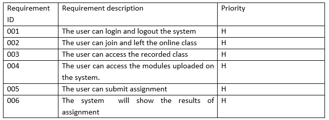
Methodology of Software Development for the Online Classes
Applications known as e-learning systems make it possible to build learning environments, integrate training materials, documentation, and communication tools, and promote engagement, cooperation, and educational management (Mohammed et al., 2021). There are various methods for producing educational content for online learning and these methods frequently employ the same phases or stages for content generation.
Rational Unified Process has the following characteristics:
Iterative Development: This necessitates iterative development of software. With each cycle, the system evolves to incorporate new ideas and capabilities, until it is fully functional and ready for rollout to the client.
Managing requirements: To do so, it is necessary to record the user's requirement in detail and to keep track of any changes made to the original demand. It examines the system and how the changes will affect it in order to decide how much weight to give to each.
Using component-based architectures: Using a component-based architecture, the system architecture is broken down into its constituent parts.
Visual software modeling: Graphical UML is used to display both the dynamic and static perspectives of the software.
Quality assurance: As a result, you can rest assured that your software is up to par with your company's standards.
Control over changes: Using a change management system and configuration management techniques and tools, it enables effective software change management.
Data Inc’s
The e-Learning roadmap from Data Inc. uses a staged approach to content production. It has been modified for use with learning management systems as well as the creation and implementation of a variety of e-Learning modules, such as dashboards and campus gateways. It combines some project management and e-learning techniques so that the organization using it can gather requirements, turn them into tasks, distribute resources, and create and implement the program.
By transferring traditional learning methods to the Internet, DATA Inc. attempts to create an e-Learning system(Dogruer et al., 2011). Nevertheless, it makes use of the advantages of the Internet, such as chat rooms, shared resources, and flexible user role definition. The formation course is now presented by DATA Inc. using Microsoft Power Point. This method includes dashboards and campus portals, both of which are crucial for online classrooms. It is a wise decision to use this program since it provides a venue for gathering resources and putting information to use, which promotes an environment that is productive for education.

Project Timeline: required
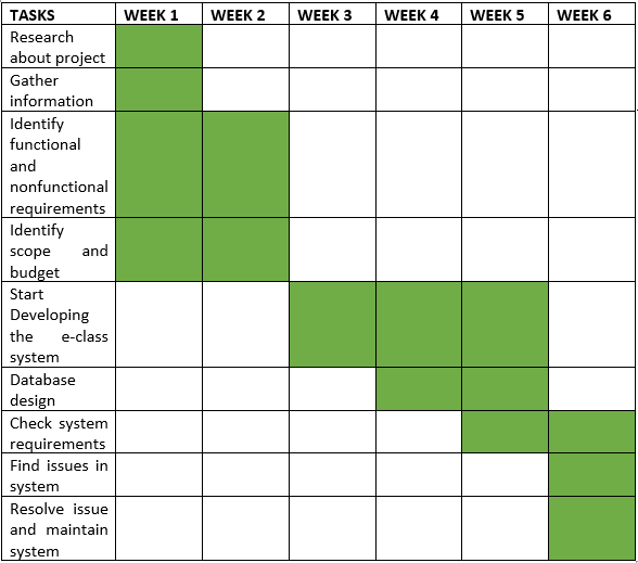
Budget
A project's budget is the sum of money set aside to achieve the project's objectives within a given time frame. Managing a project's finances effectively means staying within a predetermined budget while still accomplishing the project's objectives.
Human or Labor Resources

Equipment and Material Resource

Conclusion
Illiteracy will be a thing of the past, students won't have to travel far for this type of education, workers, parents, and many other people will be able to attend class without feeling guilty about ignoring their duties, the bias that is sometimes present between lecturers and students in physical institutions will be reduced, students will be more motivated thanks to the excitement that comes with e-learning, and parents won't have to whine about the negative effects on their children. Online classes can therefore be successful with the help of collaboration and the information acquired from the university's various stakeholders and their priorities.
REFERENCES
Dogruer, N., Eyyam, R., & Menevis, I. (2011). The use of the internet for educational purposes. Journal of Procedia - Social and Behavioral Sciences, 28, 606–611. https://doi.org/10.1016/j.sbspro.2011.11.115
Hitka, M., Štarcho?, P., Lorincová, S., & Caha, Z. (2021). Education as a key in career building. Journal of Business Economics and Management, 22. https://doi.org/10.3846/jbem.2021.15399
Junus, K., Santoso, H., Putra, P. O. H., Gandhi, A., & Siswantining, T. (2021). Lecturer Readiness for Online Classes during the Pandemic: A Survey Research. Journal of Education Sciences, 11, 139. https://doi.org/10.3390/educsci11030139
Meyer, J., & Barefield, A. (2012). Developing and Sustaining Online Education: An Administrator’s Guide to Designing an Online Teaching Program.
Mohammed, O., Rida, N., & Chafiq, T. (2021). Overview of E-Learning Platforms for Teaching and Learning. International Journal of Recent Contributions from Engineering Science & IT (IJES), 9, 21. https://doi.org/10.3991/ijes.v9i1.21111
Öncü, S., & Cakir, H. (2011). Research in online learning environments: Priorities and methodologies. Journal of Computers & Education, 57, 1098–1108. https://doi.org/10.1016/j.compedu.2010.12.009
Assignment
Effect of Australian Engineering Ethics on Professionalism and Society Assignment Sample
Question
Explain engineering professionalism and ethics in the Australian contexts
Answer
Explain The Historical Impact of Engineering On Society
Not only today but also in the past, engineering solutions have had a very significant impact on Society and the community. There have been both positive and bad implications. Positive because it enabled the development of home appliances and the purification of water; negative because it led to the development of bombs, which severely damaged the environment and whose consequences are still being felt today. Thus, the engineers' duty has changed in that they are now expected to concentrate on containing the destructive effects of human exploitation of the environment and on minimizing those effects as well. Thus, it can be claimed that engineers today have a better understanding of how their inventions may affect the environment.
The acts and events carried out by engineers worldwide have surely made Earth a better place to live. The most gratifying aspect of engineering is that it assists with resolving a number of societal issues, like alliance, safety, sanitation, and sustainability. By eminent valuable configurations that fundamentally aid in expanding and improving the haulage and living conditions of the population of the planet Earth, engineers aim to achieve the people of today. Engineering and engineering assignment help has ensured that the resources are sufficient to support the expanding population, hence promoting the further expansion of civilization (Royal Academy of Engineering., 2013).
But as time goes on, the population's influence grows and should not be disregarded. Since more than a century ago, engineers have prioritized dominating nature rather than preserving and enhancing it. Dominance caused the human race and the natural world to become estranged from one another, and it was the human race that was perceived as taking an aloof and carefree attitude toward the preservation of nature. However, engineering was ensured to leave its mark on the world through extraordinary accomplishments while neglecting the surroundings. Engineering has always focused on current breakthroughs while ignoring their ramifications for the future. As a result, while engineering has had some positive effects throughout history, the negative effects are more long-lasting. The current human race's living conditions have been enhanced by innovations like better drainage and sanitary systems, but they have also increased the human race's population. When the threat and level of spontaneous or redundant problems in the natural system were coupled with engineering systems, ignorance of the situation became apparent.
It is so obvious that although engineering has made it possible for people to live a better life while working to improve it, engineers have neglected the reality that their actions are damaging the environment and the air that humankind is breathing. As a result, it is their responsibility to combine their mechanical and methodical expertise with a greater understanding of what is known as "soft" tissues, which is outside the scope of their technical knowledge (Franquesa et al. 2015). Therefore, it is accurate to say that their work goes beyond mechanical knowledge and considers the effects that inventions and improvements have on the natural world. For instance, engineers developed motor vehicles to speed up and improve the safety of transportation. But in the process of developing the same, they overlooked two important difficulties, namely the fact that the fuel used to power these automobiles is non-renewable in nature and that they add to the rising pollution that is making the air unbreathable with each passing day. History thus serves as evidence that the impact of technology on nature and the environment is just as important as its own development.
Therefore, the perspective for teaching engineering goes beyond just the technical aspects and includes the non-technical aspects that would take into account the ecological balance and the long-term effects on Society. The primary challenge that this career currently faces is to educate those who would work to find catalysts for sustainable growth and social and economic reforms because the historical impact of engineering is so upsetting (National Academy of Engineers, 2004).
The construction of a sustainable situation and environment that offers a safe, sheltered, hale and hearty, dynamic, and sustainable way of life to all people should, therefore, be the primary goal of the engineering profession in the current scenario when examining the implications and outcomes of engineering on the community.
References:
The Social and Environmental Impact of Engineering Solutions: from the Lab to the Real World, by D. Franquesa, J. L. Cruz, C. Alvarez, F. Sanchez, A. Fernandez, and D. Lopez, is available at https://www.academia.edu/374354.
The Social and Environmental Impact of Engineering Solutions from the Lab to the Real World (Accessed on April 19 2018) (Accessed on April 19 2018)
Engineering for the Developing World, National Academy of Engineers, 2004, online at http://www.engineeringchallenges.org/cms/7126/7356.aspx (Retrieved on April 19, 2018)
Engineering in Society, published by the Royal Academy of Engineering in 2013, is online at https://www.raeng.org.uk/publications/reports/engineering-in-society (Retrieved on April 19, 2018)
Essay
Analog Vs Digital Communication Essay: A Comprehensive Analysis
Question
Task: Write a 2000-word essay contrasting the analogue and digital communication systems. Give a thorough examination of the two communication systems, including a brief description of each and a list of benefits and drawbacks. The students are required to cite at least ten articles that have undergone peer review in this essay.
Answer
Introduction
One of the most crucial components of human civilisation is communication. Without effective communication, humanity would not be where it is now. The means of communication have changed and advanced over time, just like any other technological invention. The analogue vs. digital communication essay provides a concise history of the various transmission and communication methods used by mankind. The assignment includes a thorough explanation of analogue and digital communication as well as a contrast of the two methods.
Start with the fundamental parts of every communication system in order to completely comprehend this analogue vs. digital communication essay. Any kind of communication has three primary parts, which are as follows:

Sender: The individual sending the communication is referred to as the sender.
• Channel: The medium used to transmit a message is referred to as a communication channel.
• Receiver: The point at which the message signal ends up at its final destination is called a receiver.
A signal is any message or other piece of information that is sent from the sender to the receiver through gestures, movements, sounds, etc. An energy source called a signal transmits a message through a communication channel (Bhagyaveni, Kalidoss, & Vishvaksenan, 2016). This energy takes the form of electromagnetic waves in communication networks.
There are two types of signals:
1. Analog Signals
2. Digital Signals
Analog Communication
Now that you've read this article comparing analogue and digital communication, you know what analogue communication is. Analog communication is any form of communication that uses analogue signals. In analogue signals, a continuous physical quantity with time-varying instantaneous values is represented (Veretekhina, et al., 2018). The analogue signal's amplitude changes over time, either frequently or sporadically. A sine wave is used to indicate it. Speech, sound, voice, and other types of information can all be carried via an analogue transmission.
When using analogue communication, speech, noises, or voice messages must be translated into an electrical form that may be sent to the intended recipient. An analogue signal is created from the message with the aid of a transducer. The signal is then sent through the channel to the output transducer, which transforms the analogue signal back into a human-understandable speech message.
Communication via analogue signals is only appropriate for close proximity since it is susceptible to noise, which can distort the message and make it challenging to interpret. However, analogue signals can be transferred across greater distances with the use of modulation techniques, in particular: Amplitude Modulation and Angle Modulation (Matin, 2018).
A modulator is required at the transmitter end and a demodulator is required at the reception end when utilising modulation techniques. An analogue single is multiplied by a high-frequency carrier signal during modulation, which facilitates the signal's transmission across a greater distance. The carrier signal and the analogue signal are separated to convey the original message to the receiver after the signal investigates the demodulator through the transmitting channel.
Digital Communication
In order to evaluate this Engineering essay on analogue vs. digital communication more effectively, it is time to comprehend digital communication. Digital signals are used to carry out digital communication. Any signal that contains data in a discrete and non-continuous form is referred to as a digital signal. In a digital signal, a message's values are allocated independently of its preceding values. They can be transferred across greater distances and are indicated by square waves. Additionally, digital signals are less likely to transmit with noise distortions (Channi, 2016).

An analogue signal is converted into a digital signal made up of 0s and 1s by sampling the analogue signal and encrypting it. After the analogue signal has been quantized and sampled, it is modulated using methods used for digital signals before being delivered across the channel. Once the signal has arrived at its intended location, it is demodulated and recoded into a format that the recipient can comprehend.
Pulse code modulation and delta modulation are the methods used to modulate digital signals (Sarade, 2017). The non-continuous coded pulse train made up of 0s and 1s is created from the analogue signals. It is referred to as PCM, or pulse code modulation. Repeaters are also necessary for digital communications since they strengthen the signal and extend its range. Repeaters don't just amp up the transmissions; they help reduce the noise the signal is subjected to on the channels.
Digital signals can be transmitted more easily and across greater distances. They also exhibit far less noise distortion. Due to a digital signal's non-continuous nature, the few noise distortions they encounter do not impair the signal's quality. In a digital communication system, this makes isolating and retrieving the original message simpler (Qasim, Meziane, & R.Aspin, 2018).
Digital signals move in a bit stream, which enables packetization of the signal and fast data transmission. Digital communication uses modulation and demodulation techniques to enable transmission that is more dependable and efficient.
Comparison in Analog vs Digital Communication
In this analogue vs. digital communication essay, let's avoid focusing on the key distinctions for several factors, such as cost, adaptability, efficiency, the amount of power needed, etc.
1. Equipment Cost: Because digital communication entails transforming an analogue signal into a digital signal, the process is more difficult than with analogue transmissions. It changes the kind of specific tools and equipment that are needed. As a result, digital communication is substantially more expensive overall than analogue communication.
2. Bandwidth: Both analogue and digital signals depend heavily on bandwidth for successful communication. Because their transmission range is smaller than that of digital communication, analogue signals use far less bandwidth than digital ones.
3. Synchronization Capabilities: Analog communication cannot be synchronised, however digital communication can. The efficiency of transmission is increased through synchronisation.
4. Power Required: Digital communication equipment is more expensive and complex, while analogue systems need considerably more power than digital communication systems because analogue signals have a smaller bandwidth requirement.
5. Efficiency: Analog communication technologies are less efficient than digital signals because they are more susceptible to significant observational mistakes owing to parallax and approximation. Digital signals are substantially less likely than analogue signals to be distorted by noise, which can lower the quality of the original signal. Analog transmissions are also more susceptible to noise distortions. As a result, analogue communication systems are less effective than digital ones.
6. Fidelity: A communication system's fidelity is its capacity to maintain the authenticity of the original message. Digital communication methods are more successful at maintaining the output's consistency with the message that was intended from the source during transmission.
7. Hardware Flexibility: The tools and equipment used for analogue communication are fairly hefty and larger in size, which is a significant difference between analogue and digital communication. In contrast, digital communication uses significantly smaller, lighter technology. As a result, digital communication provides greater hardware flexibility and configuration mobility.
8. Transmission: Analog signals are transmitted continuously and as waves that don't stop, but digital signals are delivered as non-continuous packets of binary data that are considerably simpler to understand. Additionally, analogue signals have a shorter transmission range than digital signals.

Pros and Cons of Analog Communication Systems
In this analogue vs. digital communication essay, there are several benefits and drawbacks that need to be considered in order to fully comprehend each side. Let's first examine the different benefits and drawbacks that analogue transmission offers:
Pros
1. Less bandwidth is required for analogue communication systems.
2. They transmit messages from source to recipient with the greatest degree of accuracy.
3. They provide a higher sound quality and are extensively used in analogue phones.
4. Compared to digital systems, they are more easier to set up.
5. Analog systems outperform digital systems by a wide margin due to the absence of quantization noise and aliasing distortions.
Cons
1. It is unable to broadcast over greater distances.
2. There could be channel noise.
3. The signal's continuity needs to be preserved
4. Digital systems cannot be added to its equipment.
5. Uses more energy
Pros and Cons of Digital Communication System
Digital systems are the opposing argument in this analogue vs. digital communication essay. The following are the main benefits and drawbacks of digital communication systems:
Pros:
1. They can transport data over greater distances, which is a plus.
2. They are reasonably simple to process.
3. The apparatus is adaptable.
4. It is extensively used and suitable for the majority of modern devices.
5. The channel multiplexing approach enables the flow of data in several formats over the same channel.
6. Considerably reduced noise distortions
7. Integrated networks are used by digital communication systems, which increases efficiency.
Cons:
1. It makes sampling and quantization problems more likely.
2. They need a lot more bandwidth to function.
3. To identify digital signals, the communication systems must be synced.
4. It costs more than analogue systems do.

What are some Analogue vs. Digital Communication Systems applications?
Both analogue and digital communication have a wide range of uses that have aided human development in a number of areas (Gupta, 2018). The areas in which the technologies are currently used are covered in the next section of this analogue vs. digital communication essay.
Analog Communication Systems
The use of analogue communications is still very much in demand, and they are crucial to our daily life. The main drawback of analogue systems, which is a limited range, can be overcome by using modulation techniques, specifically AM, PM, and FM (Mohammed & Abdullah, 2019). This provides numerous applications for analogue systems, which are frequently used. The following are some uses for analogue communication systems:
1. Audio transmission in the AM and FM bands at medium radio frequencies
2. Due to the crystal-clear speech quality of analogue systems, numerous telephone service providers continue to employ them.
3. Although many video television services still operate on analogue signals, the digital platform has gained significant traction in recent years.
4. To track the point of signal transmission, many navigation systems use analogue communication methods.
5. Analog communication technologies are still in use and capable of providing emergency services.
Digital communication Systems
Digital communication technologies are now widely used and have been incorporated into the global communication infrastructure. It is mostly due to the versatility and range it provides. There are several uses for digital communication systems, which provide better and more efficient data transmission (R.C.Dorf, et al., 2017). Here are a few examples of typical uses for digital communication systems:
1. Due to its discreteness, it is used in missile guiding systems and other military applications.
2. Digital data compressions are employed for transmission at high speeds via digital communication systems.
3. Because it transfers data in encrypted formats, it is frequently utilised in audio and voice processing.
4. Both texting and calling employ digital communication.
5. Due to its wide range and low noise distortions, digital signals are used by space research groups for all communication.
6. Digital signals are transmitted to operate the Internet. Digital communication is helpful for all of that, from doctors to banking to social media.
Conclusion
The development of modern civilisation has had a significant impact on analogue communication. It has helped the development of numerous other technological innovations. One such technological advancement made feasible by analogue communication methods is digital communication. In this analogue vs. digital communication essay, we examined the fundamental definition, significant distinctions, and uses of analogue and digital communication. Due to its benefits, digital communication is sweeping the globe and has created a wealth of new study opportunities. Although analogue communication still has numerous advantages that are unmatched and will make it important even in 2020, digital communication is unquestionably the next stage in global technical growth.
References
Bhagyaveni, M., Vishvaksenan, S., & Kalidoss, R. (2016). Analog and digital communication basics (Vol. 46). publisher, River.
H. Channi (2016). A Study Comparing Different Digital Modulation Techniques. Journal of IT and Engineering International, 4 (03).
S. Gupta (2018). textbook on the uses of optical fibre connection. PHI Learning Private Limited.
M. Matin (2018). Digital modulation systems, AM, and angle modulation. Electrical Engineers' Communication Systems, 43–69.
Abdullah, H., and Mohammed, R. (2019). use of FPGA to implement digital and analogue modulation systems. 18(1), 485-493, Indonesian Journal of Electrical Engineering and Computer Science.
A. Qasim, F. Meziane, and R. Aspin (2018). Application of digital watermarking in building user confidence in state-of-the-art medical imaging workflow reviews. 27, 45-60 of the Computer Science Review.
Whitaker, J., Roden, M., Salek, S., R.C. Dorf, Z.Wan, et al (2017). Demodulation and Modulation optical communication technology and broadcasting.
S. Sarade (2017). employing a microcontroller and the adaptive differential pulse code modulation (ADPCM) technology to compress speech 2(3), 1–9, Journal of Electronics and Communication Systems.
Veretekhina, V., Kashirin, S., Kotenev, V., Shmakova, E., A.A. Soldatov, and Medvedeva, A. (2018). processing and digitization of analogue sound signals 39.
Research
ENGR9704 Engineering Management Assignment Sample
Assignment 1 - Project Specification (group project)
Title page: The title page or cover page for the project should indicate:
• The name of your group
• Group members’ names and student ID
• Date of submission
• Topic name
• Topic code.
Table of Contents
1. Executive Summary of the main work undertaken, the achievements and other significant outcomes. Executive Summaries should not be a ‘prose of Table of Contents’ and should contain information about the background, statement of objectives, proposed solution and requirements, and description of deliverables to give a complete snapshot of the project. Ideally short and to the point, able to be read quickly to judge the viability of the project in a short viewing period. E.g., it should describe what the project is about, its key milestones, stakeholders and benefits/significance.
2. Introduction / Background.
This is used to introduce the business project, describe what has happened in the past to address the problem, and what the current status is at the time of writing the Project Specification. Purpose of the Project and Problem Statement
This section should clearly establish the benefit to the organisation of proceeding with the proposed project. It should contain:
• A description of the relevant market/industry conditions that affect the project/product
• An assessment of how the business needs are currently being met or not met (e.g. customers
currently have X we will provide a better product/service).
• An analysis of the gap between the current situation and the stated objectives (what needs to change to make your project a success).
• Identify who in the organisation is sponsoring the project and why? (or what outside organisation is sponsoring).
3. Project Overview for assignment help
This should include:
• Project Title
• Vision for the project – including goals for the project and what it is expected to deliver.
• Organisational Objectives – all projects should relate to and produce results that relate to pre- defined organisational goals. The relationship between the project and the Corporate Strategic Plan should be described.
• Scope - Develop a scope statement for the project. Use the template provided on the text companion Web site and review the sample in the text. Be as specific as possible in describing product characteristics and requirements, as well as key deliverables.
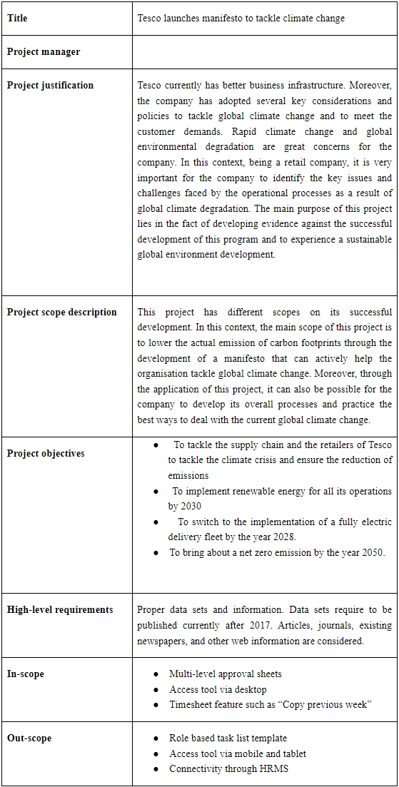
Table 1: Scope Statement
4. Critical Assumptions and Constraints
It is essential that assumptions made during the project planning process are recognised and recorded. Any requirements for specialist resources or skills should be identified here, and any dependencies that exist with other projects or initiatives.
5. Analysis of Options
This should be a high-level analysis of the possible alternatives that could be employed to bridge the gap between the current situation and what is proposed via the project.
Some options that need to be considered may include:
• Option 1 – Do nothing
• Option 2 – Undertake project
• Option 3 – Undertake alternative project
• Option 4 – The preferred option.
The advantages and disadvantages of the options can be compared in a table.
Note, that this does not necessarily need to be alternative projects (as some projects students have picked may not be suited for this type of analysis. Alternatives may also be in the form of different directions for the project to go down, such as using different materials for critical components, choosing alternative means of construction/assembly (in-house vs. outsourced), or different locations for facilities. The choice is yours for how this applies to your project.
6. Work Plan
Needs to outline project steps and phases, and major areas of work. Develop a work breakdown structure (WBS) for the project. Provide a tabular (list) version of a WBS, and a graphical version. The priority is a simple professional display of relevant information. Include a full list of tasks in the tabular version, and a condensed high-level list (if necessary) in the graphical version, to save space and make it easier to read.
7. Outputs
This needs to describe the main deliverables and outcomes that are generated by the project. Create a milestone list for this project and include at least five milestones and estimated completion dates for them.
8. Costing Section
Develop a cost estimate for the project. Estimate hours needed to complete each task (including those already completed) and the costs of any items you need to purchase for the project. Perform a Financial analysis of the intended project, include information to evaluate the potential of the project to investors (this may be included in the ‘analysis of options’ section as well in shorter detail). Use tools relevant to comparing projects such as Return on Investment, and the Net Present Value of the project.
9. Implementation Strategy
The information in this section is important. It needs to describe the main resources that will be involved as well as timelines and important milestones. Use the WBS and milestone list you previously developed to create a Gantt chart and network diagram for the project, (note that MS Project can generate both Gannt and Network Diagrams automatically from this information). Estimate task durations and enter dependencies, as appropriate. A network diagram should be included to deliver a realistic schedule. Milestones should be included as completion of major phases in the schedule and not arbitrarily defined beforehand. Once the project is well understood, the time and resources needed for its completion defined (including a realistic budget that includes the cost of the necessary contribution of time by the client, and “in-kind” cost of hours of the students. In this way, the students have a clear path to follow with sections logically dependent on each other and flowing from need to solution. Consider the resources needed for each of the tasks defined in the work plan, particularly the hours required.
10. Stakeholders
List of those to whom outputs will be delivered and a description of how each will use the benefits of the project. Related projects (or major change initiatives) that are significant for this project should be identified in this section.
11. Project Management Framework
This describes how the project will be managed, including:
? The proposed governance model (who is responsible for what?) Create a RACI chart for the main tasks and deliverables for the project.
? Quality assurance and control features of the project – consists of standards and methodology to be applied and project monitoring requirements to ensure outputs have been achieved. Create a quality checklist for ensuring that the project is completed successfully.
Also define at least two quality metrics for the project.
? Develop a communications management plan for the project. This should include:
Communication type (i.e., team meetings or project status meetings)
Objective of the communication
Medium (email, meeting, phone call)
Frequency
Audience or attendees
Who is responsible for the communication?
12. Risks
Create a probability/impact matrix and list of prioritized risks for the project. Include at least 12 risks
Solution
1. Executive Summary
The main idea behind this project is to analyse the manifesto of TESCO about climate change. In this report, a brief analysis of costing and time scale of implementation of the factors such as reducing carbon footprints, and food wastage control have been elucidated at the brief. Despite this, the report has delineated a stakeholder analysis of who is responsible for this project. Mainly three types of stakeholders have been identified in this project such as employees, local people, and government. Despite this, the impacts of the stakeholder on this project along with their roles and responsibilities have also been set forth in their report. In addition to it, the report further convened a brief idea about the RACI model where the report segmented people and their responsibilities with the help of four factors: Responsibilities, Accountability, Consultation, and Informed. At long last, the report identified two risks such as the effort to increase public awareness and climate change denial that the organisation TESCO can face during implementing their manifestation of climate change, In Addition, the report further segmented the risk as per their priority and recommended some approaches to extenuate those risks. Despite this, the report highlights other various factors such as the role of the zero deforestation soy initiative, the role of artificial intelligence in supply chain management and work plans such as project scopes, identification of the problems, and the final outcome of the project in the report.
2. Introduction or Background
2.1. Purpose of the Project
The main purpose of this project is to develop a manifesto for the purpose of tackling climate change. In this context, currently, the rapid climate change and environmental diversity loss are one of the greatest concerns of the UK government. As per the collected data, it is evident that the main sea level of the UK has risen significantly up to 1.4mm per year since 1910 due to the increasing business operations, economic activities, and the global transport system (Moore et al., 2019). Due to rapid climate change, the sea surface temperature of the UK has risen to .3 degree Celsius and 0.6-degree Celsius warmer climate. In order to mitigate this global concern and to expect more sustainable and global environment development, it is very important for the country to find the best possible options. Tesco is currently following the principle of developing the global climate through the application of developing a manifesto. In this context, through the application of this manifesto, it can be possible for the company to contribute much to the global environment development (Castle and Hendry, 2020). The main purpose of this project lies in the fact of developing evidence against the successful development of this program and to experience a sustainable global environment development.
2.2. Problem Statement
Rapid climate change and global environmental degradation are great concerns for the company. In this context, being a retail company, it is very important for the company to identify the key issues and challenges faced by the operational processes as a result of global climate degradation. In this context, the main issue is the increasing carbon emission from the manufacturing outlet of the company. Due to more emissions of carbon footprints, the company is facing several restrictions and issues in its current business operations (Raven and Wagner, 2021). Therefore, it is very important for the company to understand the current business applications and reshape the business accordingly.
The company needs to implement the latest technologies and make constant innovations in its existing system. Through the application making the entire business updated, it can be possible for the company to find the best possible ways, manage sustainable processes, and expect the minimization of carbon footprints from the manufacturing outlets (Nassaryet al., 2022). Moreover, it can also be possible for the company to expect successful ventures in their long-term and short-term goals for the development of the global environment.
Tesco currently has better business infrastructure. Moreover, the company has adopted several key considerations and policies to tackle global climate change and to meet the customer demands. As per the current marketing trends, customers are reliable on sustainable products and services with high shelf life, low cost, and eco-friendly. For this reason, Tesco has reduced carbon footprint emission significantly and it’s trying to practise zero carbon emission by 2050 to add more value to the global consumers. Tesco has also paid focus on the feedback system development for the purpose of making constant changes in the quality of the offering products for the purpose of meeting customer interests and demands.
The main gap between the current situation and the organisational objectives is the lack of proper considerations in the supply chain management and manufacturing output. As per the objectives, Tesco will bring out zero carbon emission by 2050 and to develop a sustainable supply chain. Tesco has initiated the process and adopted the implementation of a manifesto to tackle global climate change and to develop the supply chain.
The company needs to address UN goals and conduct accordingly. In order to raise more capital, the company needs effective sponsors. For this reason, it is very important for Tesco to tie up with multinational companies offering similar services in the global marketplace.
3. Project Overview
3.1. Project Title
Tesco launches manifesto to tackle climate change
3.2. Vision for the Project
The main vision of the project is to set different objectives for the purpose of maintaining the successful development of the entire project. In this context, the principal vision of the project is to tackle the rapid climate change in the UK. Therefore, through the application of maintaining a proper strategy and plan, it can be possible for the company to pay close attention to the details of the development of an effective policy to reduce the significant amount of carbon footprint reduction. Moreover, through the application of a proper plan and policy, it can also be possible for the business to bring out net zero emission of carbon footprints by the year 2050 and to effectively develop the supply chain.
3.3. Organisational Objectives
The objectives set out by the organisation are mainly to facilitate Tesco Plc to achieve climate change in a better manner. The objectives set out through the manifesto of Tesco to tackle climate change are as follows:
? To tackle the supply chain and the retailers of Tesco to tackle the climate crisis and ensure the reduction of emissions
? To implement renewable energy for all its operations by 2030
? To switch to the implementation of a fully electric delivery fleet by the year 2028.
? To bring about a net zero emission by the year 2050.
3.4. Scope Statement
This project has different scopes on its successful development. In this context, the main scope of this project is to lower the actual emission of carbon footprints through the development of a manifesto that can actively help the organisation tackle global climate change. Moreover, through the application of this project, it can also be possible for the company to develop its overall processes and practice the best ways to deal with the current global climate change.
There are several considerations included in this project that help the particular project to get successfully developed (Krogstrup and Oman, 2019). The project manager has been able to make the project accordingly through the application of identifying all the risks, timelines, and outputs. A proper digital timeline and alternative marketing operational strategies have been identified. In this way, this project can lead to the initiation of many more projects like this.
4. Critical Assumptions and Constraints
A high level of climate awareness has been implemented in the UK to help the country achieve net zero emissions. It has been observed that several companies in the country have undertaken climate control manifestos. From the studies of Gannon et al., (2022), it can be mentioned that the major constraints that can be faced in the development of a climate manifesto involve the capacity of the people to adapt to the change. From the research of Moussa et al., (2019), it has been found that the process of incorporating change on a wider basis becomes difficult since people are more comfortable with the older ways. Moreover, another important constraint of implementing a climate change manifesto involves limited knowledge of technology paired with limited awareness.
From the reports of the company, it has been observed that the critical assumptions that have been made by the company involve the following:
? A complete transition toward the use of electric vehicles would help in tackling carbon emissions.
? Creating a better basket for the customers and the planet would help in accelerating the process of climate control (Tescoplc.com, 2021).
? Improving the issues of food production would lead to preventing climate change in a better manner.
? Working with the suppliers in order to scale the technologies and target the causes of agricultural emissions would help in improving the climate manifesto.
Overall, from the identification of the constraints and the assumptions, it can be said that the planning process needs to be done in such a way that all the constraints are overcome and the assumptions are met. It needs to be mentioned that the implementation of project planning tools needs to be made so that the dependencies of the tasks can be identified in a better manner.
5. Analysis of the Options
5.1. Option 1: Zero-Deforestation Soy Initiative
Considering all the alternatives for tackling the climate change manifesto, Sainsbury’s has implemented a “Zero-deforestation soy initiative” (Sainsburys.co.uk, 2022). From the reports, it has been observed that this initiative helps in the protection of forests. It can be mentioned that the management of the financial incentives has been done by the company in such a manner that they are able to fund the Brazilian farmers. Therefore, it must be stated that choosing this option significantly contributes to environmental management. A 12-month trial phase was started, and the results have assisted in encouraging Brazilian farmers to protect the country's native Cerrado vegetation as well as the preservation of the water quality and the decline in biodiversity.
5.2. Option 2: Recyclable Packaging
The sustainability commitments of ASDA can be considered another important option for the management of the sustainability process. As per the reports of the company, it can be mentioned that the initiative undertaken by the company is to implement sustainable packaging. The company has been observed to reduce the total packaging weight by 27% (Asdasupplier.com, 2022). As one of Walmart's sustainability goals, it should be noted that the company has made a strong commitment to achieving 100% package recycling by 2025.
5.3. Option 3: Blockchain or AI in the Supply Chain
Certain small retail SMEs have been trying to comply with the “Forest Risk Rules” in order to prevent deforestation measures. From the recent reports, it has been observed that the UK government has been seen to aim at preventing deforestation rates in the country (Retail-week.com, 2021). Overall, in compliance with the UK rules and regulations, it can be mentioned that the development of agile supply chains and the implementation of technology such as blockchain and AI help in reducing waste at all levels of the supply chain. Overall, it needs to be mentioned that the implementation of these options helps in increasing the sustainability of the companies.
However, a negative aspect of the SME has been observed to be in the funding aspect. Hence, the adoption of technology has been observed to be highly difficult for companies.
5.4. Option 4: Reduction of Carbon Footprints
It has been noted that Aldi supermarket has adopted sustainable tactics like reducing operational emissions. The reports have been observed to have opted for a reduction of plastic pollution. The most innovative option implemented by the mentioned company is the implementation of smart shopping (Corporate.aldi.us, 2021). The reduction of carbon footprints has been the main aim of the mentioned company.
5.5 Advantages and Disadvantages of the options
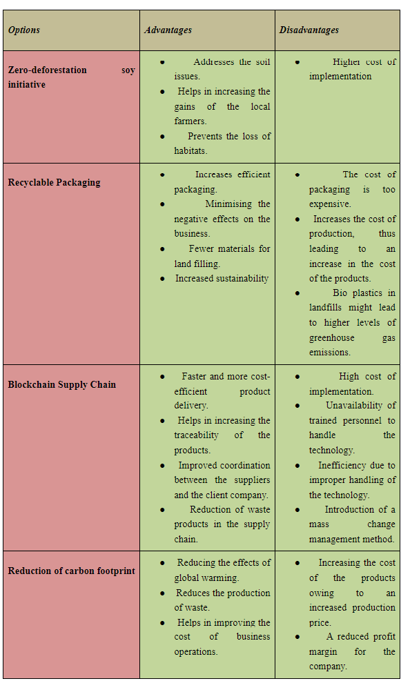
Table 2: Comparison Table for the Options Discussed
From the above table, it can be seen that the alternative options have almost similar kinds of disadvantages. Therefore, it can be said that every green or sustainable strategy raises the cost of production.
6. Work Plan
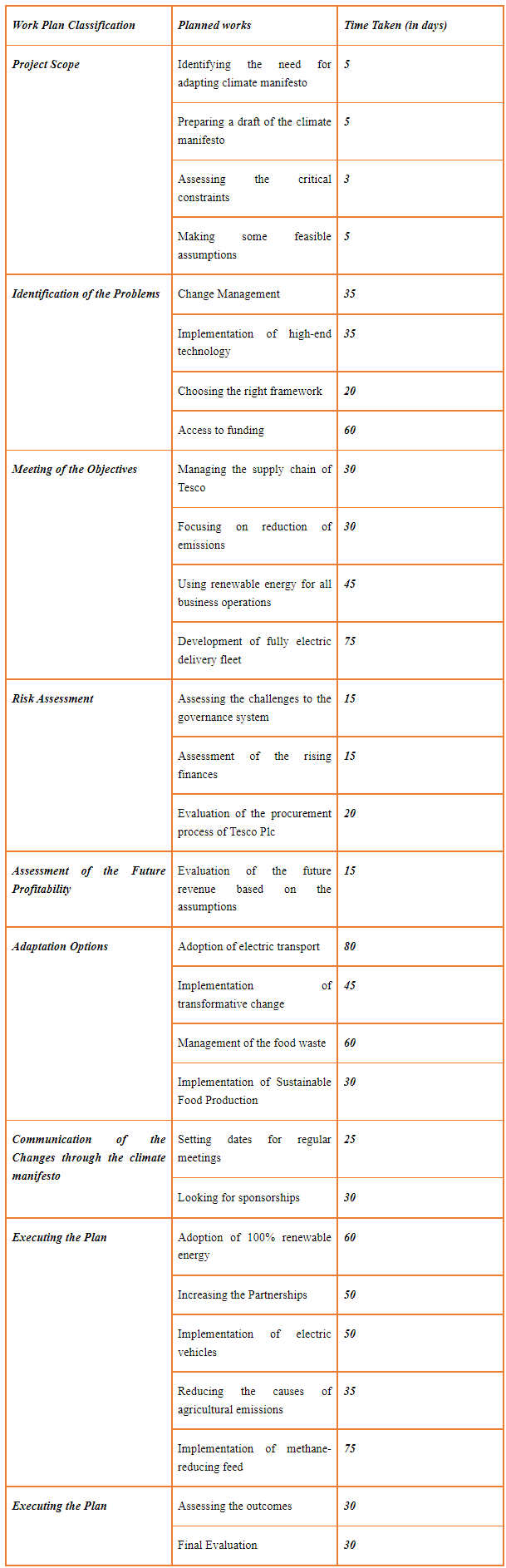
Table 2: Manual Work Plan (Tabular)
From the studies of Matheson et al., (2019), it can be mentioned that the work plan is important to identify the chronological order of undertaking a particular work. Additionally, it can be mentioned that the work plan is important as it helps in identifying the major areas of priority in a project.
The work plan, in this case, has been broadly classified under the following groups:
? Project Scope
? Identification of the problems
? Meeting the Objectives
? Risk Assessment
? Achieving Future Profitability
? Adaptation Options
? Communicating the Changes
? Executing the Plan
? Final Outcome
The work breakdown structure as derived from Project Libre has been represented in the following image.
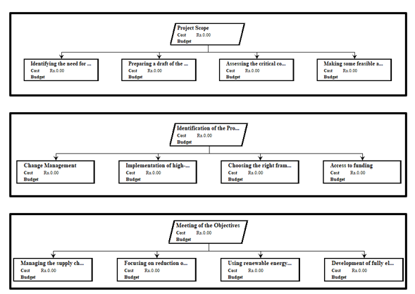
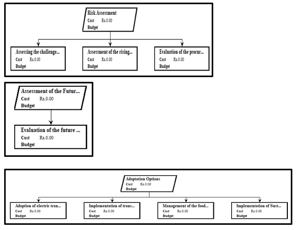
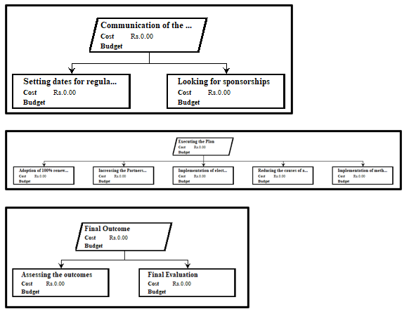
Figure 1: Work Breakdown Structure
From the work breakdown structure, it can be seen that the priority of the tasks involves assessing the important aspects of the work breakdown structure. As seen in the present case, it can be mentioned that the process of assessing the risks and evaluating the financial aspects of implementing the changes can be considered the most important. Overall, the evaluation process of the climate manifesto needs to be considered based on these aspects.
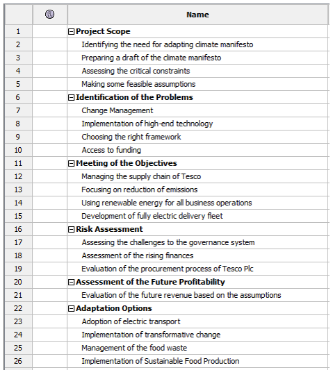
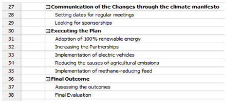
Figure 2: Digital Work Plan (tabular)
7. Outputs
Milestones
There are 9 different milestones that are going to be achieved through the successful development of this project. In this context, there are different durations decided to meet each milestone. The entire work starts on 28.09.22 and will end on 22.07.26. Each milestone is going to be achieved through the application of dividing each task into sub-tasks. All these milestones are identified as a result of the plan and processes being set up by the project manager. It is very important to consider every step for the purpose of developing this project accordingly.
? Project Scope: 5.9.22 to 29.9.22
? Identification of the problems : 29.9.22 to 27.4.23
? Meeting the Objectives: 27.4.23 to 4.1.24
? Risk Assessment: 4.1.24 to 14.3.24
? Achieving Future Profitability: 14.3.24 to 4.4.24
? Adaptation Options: 4.4.24 to 30.1.25
? Communicating the Changes: 30.1.25 to 17.4.25
? Executing the Plan: 17.4.25 to 30.4.26
? Final Outcome: 30.4.26 to 11.6.26
8. Costing section
8.1 Cost estimate
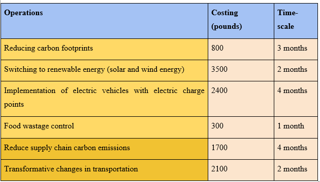
Table 3: Cost analysis
(Source: Self-developed)
8.2 Financial analysis
In order to accomplish the project total cost has been estimated at £10,800 and the total time frame has been kept for the entire project completion is 4 months. During the entire project,
ROI or Return on investment for this project will be calculated with the help of
Where
R is the return on investment
Vf is considered as the final value which includes dividends and interest
Vi=initial value
ROI will be more than 10, which can be considered a good investment for the project by the organisation.
The calculation for NPV or Net Present value will be calculated with the help of the formula:

Where Rt stands from net cash flow at time t
And i=discount rate
t is the time frame
NPV or the Net Present value for the project is Zero which clearly indicates that TESCO can expect a profit and should move forward with the investment. NPV above zero signifies inflows are greater than outflows therefore; it will help the organisation earn a profit.
9. Implementation Strategy
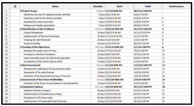
Figure 2: Digital timeline
(Source: Created by the learner)

Figure 3: Digital timeline
(Source: Created by the learner)
The entire project is developed through the application of developing a digital timeline of the entire project. In this context, through the application of a digital timeline, it is possible for the project manager to include all tasks and schedules accordingly based on the desired timeline and duration. The entire project has different phases. In this context, the first phase is project scope identification. It is followed by the identification of the objectives and the meeting of the objectives. Risk management and assessment of future profitability are also done through the application of developing the digital timeline (Cullis et al., 2019). The fourth step of the Gantt chart is the adaptation options which refer to the adaptation of electric transport and other considerations. The next step is the communication plan which involves the practice of regular communication within the project management. Execution of the plan is also done through the application of considering the expected dates and times of the entire process. In this way, the outcome is determined and thus the project is developed.
Project scope: identification, preparation, Assessment of the critical constraints, and making feasible assumptions.
Identification of problems: Change management, Choosing framework, accessing funding.
Meeting the objectives: Manage the supply chain, focus on reduction of emissions. Moreover, use of renewable energy, and development of electric fleet to meet the objectives.
Risk assessment: accessing challenges, finances, governance issues, and procurement process.
Assessment of future profitability: evaluation of future revenue.
Adaptation outcomes: electric transport, management of food waste, implementation of sustainable food production.
Communication of the changes through the climate manifesto: Setting dates, looking for sponsors.
Execution of the plan: increasing partnerships, implementation of methane reducing feed, implementation of electric vehicles.
Final outcome: Assessing the outcomes, final evaluation.
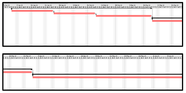
Figure 4: Gantt chart
(Source: Created by the learner)
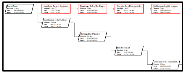
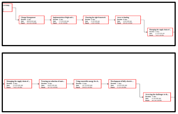
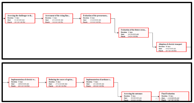
Figure 5: Network diagram
10. Stakeholders analysis
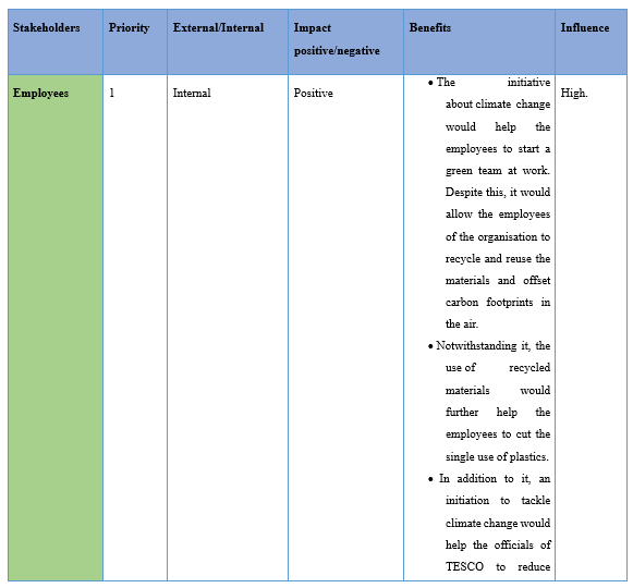


Table 4: Stakeholder’s analysis
11. Project Management framework
11.1 Governance Model (RACI model)
R= responsible
A=accountable
C=Consulted
I=informed

Table 5: RACI model
(Source: Self-Developed)
11.2 Quality assurance and checklist with two quality matrices
As per the views of Fernandes et al. (2022) quality assurance can be envisaged as a process of determining and analysing whether products or services meet with the specific requirements or not. Considering the case study, process control will be considered for the project as a part of quality assurance.
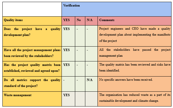
Table 6: Quality assurance
11.3 Communication management plan
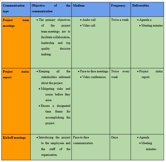
Table 7: Communication management plan
12. Risks
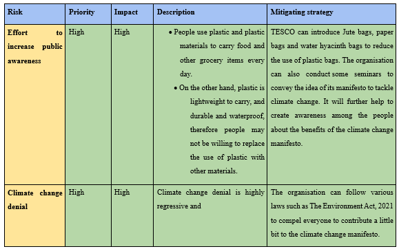
Table 8: Risk Matrix
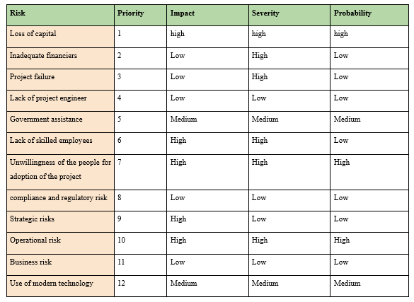
Table 9: Risk Register
13. Conclusion
The primary idea behind the project is to prepare a manifesto to tackle climate change and for this, the organisation has taken several approaches such as making a risk management plan, doing stakeholders analysis and preparing a budget to estimate the cost of the project implementation. The project also confabulated some developing evidence against the successful development of this program and to experience a sustainable global environment development. Despite this, the report has critically analysed various constraints that can arise during the project implementation and based on the risk proposed some mitigating strategies. Further, the report has confabulated the advantages and disadvantages of the zero-deforestation soy initiative, recyclable packaging, blockchain in the supply chain and reduction of carbon footprints with proper illustrations.
References
Asdasupplier.com, 2022. Our Sustainability Commitments. Available at: https://asdasupplier.com/responsibility/our-sustainability-commitments [Accessed on 05-09-2022]
Brock, A., Kemp, S. and Williams, I.D., 2022. Personal Carbon Budgets: A Pestle Review. Sustainability, 14(15), p.9238.
Castle, J.L. and Hendry, D.F., 2020. Climate econometrics: an overview. Foundations and trends® in econometrics, 10(3-4), pp.145-322.
Corporate.aldi.us, 2021. ALDI Tops the Sustainability Chart. Available at: https://corporate.aldi.us/en/corporate-responsibility/sustainability/#:~:text=ALDI%20achieved%20this%20 ranking%20as,recyclable%20or%20compostable%20by%202025. [Accessed on 05-09-2022]
Cullis, J.D., Horn, A., Rossouw, N., Fisher-Jeffes, L., Kunneke, M.M. and Hoffman, W., 2019. Urbanisation, climate change and its impact on water quality and economic risks in a water scarce and rapidly urbanising catchment: case study of the Berg River Catchment. H2Open Journal, 2(1), pp.146-167.
Fernandes, M.R., Donders, K. and Loisen, J., 2022. Ibermedia as a collaborative space for film co-production policy? A stakeholder analysis on decision-making processes. Communication & Society, pp.137-153.
Gannon, K.E., Castellano, E., Eskander, S., Agol, D., Diop, M., Conway, D. and Sprout, E., 2022. The triple differential vulnerability of female entrepreneurs to climate risk in sub?Saharan Africa: Gendered barriers and enablers to private sector adaptation. Wiley Interdisciplinary Reviews: Climate Change, p.e793.
Krogstrup, S. and Oman, W., 2019. Macroeconomic and financial policies for climate change mitigation: A review of the literature.
Matheson, E., Minto, R., Zampieri, E.G., Faccio, M. and Rosati, G., 2019. Human–robot collaboration in manufacturing applications: A review. Robotics, 8(4), p.100.
Moore, F.C., Obradovich, N., Lehner, F. and Baylis, P., 2019. Rapidly declining remarkability of temperature anomalies may obscure public perception of climate change. Proceedings of the National Academy of Sciences, 116(11), pp.4905-4910.
Moussa, L., Garcia-Cardenas, V. and Benrimoj, S.I., 2019. Change facilitation strategies used in the implementation of innovations in healthcare practice: a systematic review. Journal of Change Management, 19(4), pp.283-301.
Nassary, E.K., Msomba, B.H., Masele, W.E., Ndaki, P.M. and Kahangwa, C.A., 2022. Exploring urban green packages as part of Nature-based Solutions for climate change adaptation measures in rapidly growing cities of the Global South. Journal of Environmental Management, 310, p.114786.
Raven, P.H. and Wagner, D.L., 2021. Agricultural intensification and climate change are rapidly decreasing insect biodiversity. Proceedings of the National Academy of Sciences, 118(2), p.e2002548117.
Retail-week.com, 2021. Why retailers must be mindful of the impending Environment Bill. Available at: https://www.retail-week.com/retail-voice/why-retailers-must-be-mindful-of-the-impending-environment-bill/7039790.article?authent=1 [Accessed on 05-09-2022]
Sainsburys.co.uk, 2022. Zero-deforestation soy initiative underway with major UK supermarket backing. Available at: https://www.about.sainsburys.co.uk/news/latest-news/2022/02-08-2022-zero-deforestation-soy-initative [Accessed on 05-09-2022]
Schlund, D., Schulte, S. and Sprenger, T., 2022. The who’s who of a hydrogen market ramp-up: A stakeholder analysis for Germany. Renewable and Sustainable Energy Reviews, 154, p.111810.
Tescoplc.com, 2021. Tesco sets out its climate “manifesto” ahead of the crucial COP26 Conference in Glasgow. Available at: https://www.tescoplc.com/news/2021/tesco-sets-out-its-climate-manifesto-ahead-of-crucial-cop26-conference-in-glasgow/#:~:text=If%20we%20are%20to%20 safeguard,a%20net%2Dzero%20future.%E2%80%9D [Accessed on 05-09-2022]
Research
ENGR8762 Networks and Cybersecurity Assignment Sample
Assignment Brief
This assignment contributes 20% of your overall assessment for the topic. The grading for this assignment will be according to the University rating scheme [HD, DN, CR, P, F].
This assignment has two parts: Part A has 6% Marks, and Part B has 14% Marks.
Before you submit your assignment, you must complete the Academic Integrity module ACINT001with full marks. This is to ensure you have a good understanding of the issues of contract cheating, plagiarism, falsification, and collusion. Your submission will be automatically scanned by Turnitin for similarity. Your submission should have a similarity of less than 20%.
Submission
Due Date: Friday 29th Oct 2021 by 5 pm.
For Part A, you should provide a table (as per the example given on the next page), which addresses the threat category, controls, description, classification, and type.
For Part B, you should write a research report. The research report must have at least 1500 words but not more than 2500 words.
The assignment should be submitted as a single PDF file to the assignment space on the topic FLO page for assignment help
Late Submission
As per the official Statement of Assessments Methods (S2-2021) for this topic.
Part A: Threat classification and mitigation (6% of Total)
For the following Threat Categories, 1) Explain the threat, 2) which type of Control should be put in place for mitigation, 3) classify the controls as Process (Administrative), Product or Physical, 4) State the type of controls whether it will Prevent, Detect, Correct or Compensate. Do provide the references.
Threat Categories:
1. Impersonation attacks
2. Phishing attacks assisted with deep fake
3. Cloud Jacking
4. Ransomware attacks
5. Smishing attacks
6. DNS tunneling
Part B: Research report (14% of Total)
The topic for research is the latest security Threats. Sections on these threats include the following:
• Artificial intelligence enhanced cyber threats
• Fake news
• Ransomware attacks
• Machine learning poisoning
• Smart contract hacking
• Deep fake
• Application programming interface (API) vulnerabilities
• Internet of Things based Attacks
• Cloud vulnerabilities
• Vehicle Cyberattacks
• Threats to election
Select one of the above threats and find eight relevant papers which assist someone in developing a network threat taxonomy.
Compose an annotated bibliography of research papersthatrelate to the issue, soyour annotated bibliography will help you (and others) to have a good resource to evaluate and think about the relevance and quality of material on the topic. An example of an annotated bibliography is given at the link
https://digitalcommons.kennesaw.edu/cgi/viewcontent.cgi?referer=https://scholar.google.com/&httpsredir=1&article=1011&context=jcerp
Make sure that the information meets the topic's requirements and is from a reliable and academically respected source. Website references are not permitted unless the website is authoritative, e.g., CERT, NIST etc. You can use google scholar, IEEE Xplore digital library or ACM digital library for searching the articles.
What is an annotated bibliography?
An annotated bibliography is a list of citations to books, articles, and documents. Each citation is followed by a brief (usually about 150 - 300 words) descriptive and evaluative paragraph, the annotation. The purpose of the annotation is to inform the reader of the relevance, accuracy, and quality of the sources cited.
Annotations are NOT abstracting
Abstracts are the purely descriptive summaries often found at the beginning of scholarly journal articles or in periodical indexes. Annotations are descriptive and critical; they expose the author's point of view, clarity and appropriateness of expression, and authority.
General Instructions
The annotated bibliography is to be produced using a word processor and the EndNote reference database (or any other reference database). The submitted document must be in PDF or Word format.
The Process
Creating annotated bibliography calls for the application of a variety of intellectual skills: concise exposition, succinct analysis, and informed library research.
Solution
Part-A
The tables for threat categories along with the control and classification is shown below:
.png)
Part-B
Title
A Literature Review on Internet of Things-Based Attack
Abstract
Internet of Thing is one of the widely used platforms for transacting data. Several cloud-based applications are operated through the implication of the Internet of Things. Thus, it is one of the most demanding medium for information interchange. Millions of users are connected with this network by accessing the cloud-based application either from mobile or computer. Apart from its ease of access and platform-friendly to use, it has some security issues. As most of the users are connected with such networks for accessing the applications and services, cybercriminals obtain a feasible way to attack the connected devices and the network by penetrating malicious elements. Using this process, they use to get access to the user device and the organizational devices such as server, database etc. This causes the data and financial breach to the users and thus, it is essential to restrict the penetration of malicious elements into the network. Many researchers have proposed their methodologies and model for the prohibition or restriction to the penetration of malicious elements in the Internet of Things Network. Some of the important researches will be reviewed and discussed in this section.
Annotated Bibliography and Summarization
Annotated Bibliography
Cong, P., 2019. Spam DIS Attack Against Routing Protocol in the Internet of Things. International Conference on Computing, Networking and Communications (ICNC), pp. 198-201.
The author of this research belongs to the Department of Computer Sciences and Electrical Engineering at Marshall University, Huntington, USA. He has proposed the model to detect the DDoS attack in the Internet of Things network. They have detected that there are different types o malicious against available for DDoS attacks and one of the newest attack types is Spam DDoS. They have faced the primary challenge to detect the features of Spam DIS attack and have observed that most of this attack is subjected to the network routing protocol. So, they have researched and proposed the model through which the new type of DDoS attack that is DIS can be detected and the Internet of Things network can be protected.
Notes: This research produces a clear idea about the identification of DIS threats and the procedure of identification in the Internet of things Network.
Suryani, V., Sulistyo, S. & Widyawan, 2018. The Detection of On-Off Attacks for the Internet of Things Objects. International Conference on Control, Electronics, Renewable Energy and Communications (ICCEREC), pp. 1-4.
The authors of this research belong to the universities of Indonesia. They have researched on the Internet of Things objects that generally behave harmless while at the time of interaction with others. However, those interactions are done in a trust-based system where there is the possibility of an ON-OFF attack that can breach the user data silently. They have primarily faced challenges in the identification of trust-based and on-off attacks in the Internet of Things. They have proposed the model to detect and restrict trust-based and on-off attacks in the Internet of Things Network.
Notes: This research paper states the process of trust-based and on-off attacks in the Internet of Things Network and the procedure of detection and mitigation.
Kamaldeep, Malik, M. & Dutta, M., 2017. Contiki-based mitigation of UDP flooding attacks in the Internet of things. International Conference on Computing, Communication and Automation (ICCCA), pp. 1-5.
The authors of the research belong to India and have researched the DDoS attack that can be done by affecting User Datagram Protocol. They have emphasized the Contiki operating system and investigated the attack process. They have reviewed the previous research papers and identified that there are different types of attacks that are present in the domain of DDoS. One of the new and different types of DDoS attacks on which they have investigated was due to the effect of User Datagram Protocol in the said operating system. They have faced the primary challenge to identify the feature of that attack. Thus, they have designed and implemented the attack process using the Cooja simulator in the Contiki operating system. After that, they have proposed the solution for the mitigation process of that attach in Contiki operating system.
Notes: The researchers have demonstrated the attack type and the features of the attack on User Datagram Protocol along with the mitigation process.
Choudhary, S. & Kesswani, N., 2018. Detection and Prevention of Routing Attacks in Internet of Things. 12th IEEE International Conference On Big Data Science and Engineering (TrustCom/BigDataSE), pp. 156-159.
The authors of the research belong to India and have researched the DDoS attack on different routing protocols in the Internet of Things Network. It is to be mentioned that there are different types of routing protocols are available which are used for different purposes in the Internet of Things Network. Thus, the process of attacks is also different in these cases. Thus, they have faced challenges in identifying the procedure of attack for different protocols. They have proposed the methodology for the detection of different types of threats using Key Match Algorithm and Cluster-Based Algorithm which have been executed through Matlab Simulator.
Notes: In this research, the authors have shown and demonstrated the detection process of the threats for different types of protocols in the Internet of Things Network.
Shim, K.-A., 2019. Universal Forgery Attacks on Remote Authentication Schemes for Wireless Body Area Networks Based on Internet of Things. IEEE Internet of Things Journal, pp. 9211 - 9212.
The author of this research belongs to the University in South Korea. He had observed that wireless networks that are patched with the Internet of Things can be hacked using a DDoS agent. He had faced the challenge to detect the features of the attack so that he can propose the mitigation policy. After detecting the type of attack, he had proposed a Heterogeneous Remote Anonymous Authentication Protocol through which the attack in the Internet of Things Network can be detected.
Notes: He had demonstrated the Heterogeneous Remote Anonymous Authentication Protocol for the detection of threats in the Internet of Things Network.
Sriram, S., Vinayakumar, R., Alazab, M. & KP, S., 2020. Network Flow based IoT Botnet Attack Detection using Deep Learning.
According to the authors, administrations over the entire world are positively endorsing smart city requests to increase the superiority of daily-life actions in urban zones. Smart cities contain internet-related devices that are applied by processors such as traffic control, power grid, health care, water treatment, and many more. Each of these applications helps to improve its efficiency. The development in the number of Internet-of-things (IoT) is completely focused on botnet attacks. That is because of the rising tendency of Internet-enabled strategies. This article tries to suggest deep learning which depends upon a botnet detection system that works on network traffic movements to offer a progressive cyber-safety resolution to Internet-of-things devices as well as smart city requests.
Note: The authors of the research have demonstrated the type of attack and proposed the mitigation policy for it.
Chen, S.-C., Chen, Y.-R. & Tzeng, W.-G., 2021. Effective Botnet Detection Through Neural Networks on Convolutional Features. [Online]
The authors of the research belong to China. According to them, botnets is one of the prime threats related to internet-related cybercrimes for example spreading spam, DDoS attacks, and thefts precious information and data, according to the understanding of the research presentation it is quite evident that identifying modern botnets in recent years is becoming quite difficult to be found as well. Therefore, the project aims to present a machine learning method that can help detect the P2P botnet with the help of flow-based features.
Notes: The researchers have demonstrated the attack in the Internet of Things network that is caused by Botnet.
Wang, J., Liu, Y., Su, W. & Feng, H., 2020. A DDoS attack detection based on deep learning in software-defined Internet of things. IEEE 92nd Vehicular Technology Conference (VTC2020-Fall), pp. 1-5.
The researchers belong to the Universities in China. They have researched and emphasized different types of attacks in the software-defined Internet of Things. They have faced the primary challenges of identifying the typical attack types and behaviors. They have designed a Software-Defined Internet for Thing Network using the components like a controller, switches etc. and used a Deep Learning algorithm to detect the threats there.
Note: In this research, the authors have designed a realistic model for the detection of threats using Deep Learning.
Summarization
The summarization of the reviews of the previous researches are shown below:
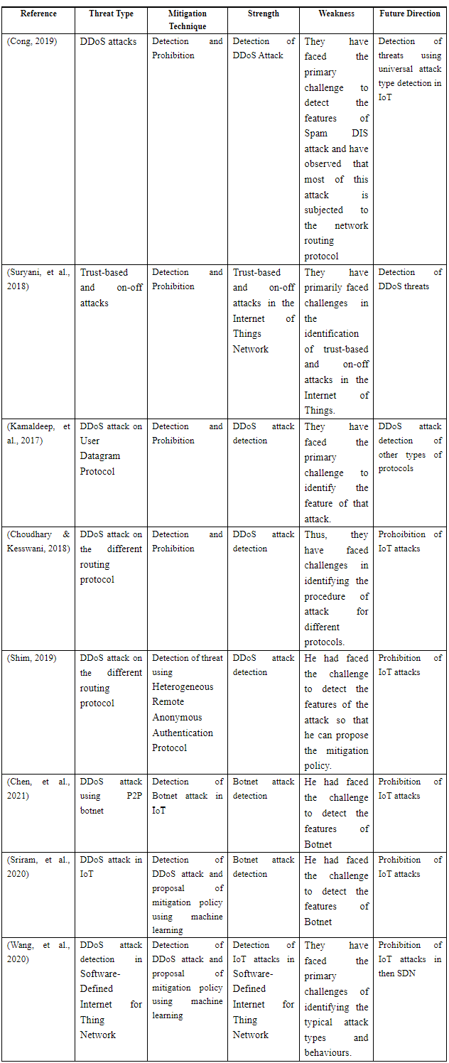
References
Agarkar, S. & Ghosh, S., 2020. Malware Detection & Classification using Machine Learning. IEEE International Symposium on Sustainable Energy, Signal Processing and Cyber Security (iSSSC), pp. 1-5.
Chen, S.-C., Chen, Y.-R. & Tzeng, W.-G., 2021. Effective Botnet Detection Through Neural Networks on Convolutional Features. [Online]
Available at: https://.ieee.org/document/8455930
Chen, Y., Jin, B., Yu, D. & Chen, J., 2018. Malware Variants Detection Using Behavior Destructive Features. 2018 IEEE Symposium on Privacy-Aware Computing (PAC).
Choudhary, S. & Kesswani, N., 2018. Detection and Prevention of Routing Attacks in Internet of Things. 12th IEEE International Conference On Big Data Science And Engineering (TrustCom/BigDataSE), pp. 156-159.
Cong, P., 2019. Spam DIS Attack Against Routing Protocol in the Internet of Things. International Conference on Computing, Networking and Communications (ICNC), pp. 198-201.
Jin, X. et al., 2020. A Malware Detection Approach Using Malware Images and Autoencoders. IEEE 17th International Conference on Mobile Ad Hoc and Sensor Systems (MASS), 8(2), pp. 172-177.
Kamaldeep, Malik, M. & Dutta, M., 2017. Contiki-based mitigation of UDP flooding attacks in the Internet of things. International Conference on Computing, Communication and Automation (ICCCA), pp. 1-5.
Kuruvila, A. P. & Basu, S. K. &. K., 2020. Analyzing the Efficiency of Machine Learning Classifiers in Hardware-Based Malware Detectors. IEEE Computer Society Annual Symposium on VLSI (ISVLSI), pp. 452-457.
Murali, R., Ravi, A. & Agarwal, H., 2020. A Malware Variant Resistant To Traditional Analysis Techniques. International Conference on Emerging Trends in Information Technology and Engineering (ic-ETITE), pp. 1-6.
Nisha, D., Sivaraman, E. & Honnavalli, P. B., 2019. Predicting and Preventing Malware in Machine Learning Model. 10th International Conference on Computing, Communication and Networking Technologies (ICCCNT), pp. 1-5.
Shim, K.-A., 2019. Universal Forgery Attacks on Remote Authentication Schemes for Wireless Body Area Networks Based on Internet of Things. IEEE Internet of Things Journal, pp. 9211 - 9212.
Sriram, S., Vinayakumar, R., Alazab, M. & KP, S., 2020. Network Flow based IoT Botnet Attack Detection using Deep Learning. s.l.:s.n.
Suryani, V., Sulistyo, S. & Widyawan, 2018. The Detection of On-Off Attacks for the Internet of Things Objects. International Conference on Control, Electronics, Renewable Energy and Communications (ICCEREC), pp. 1-4.
Wang, J., Liu, Y., Su, W. & Feng, H., 2020. A DDoS attack detection based on deep learning in software-defined Internet of things. IEEE 92nd Vehicular Technology Conference (VTC2020-Fall), pp. 1-5.
Research
MIS604 Requirements Engineering Assignment Help
Assignment Brief
Individual/Group - Individual
Length 1500 words (+/- 10%)
Learning Outcomes
The Subject Learning Outcomes demonstrated by successful completion of the task below include:
a) Demonstrate methods for eliciting, analyzing, documenting, and maintaining requirements in an organizational context.
b) Synthesize key principles of requirements management and communicate to stakeholders in order to solve problems.
Submission - Due by 11:55pm AEST/AEDT Sunday end of Module 2.2
Weighting - 25%
Total Marks - 100 marks
Task Summary
This Assessment requires you to respond to a case study. The same case study will be used for all three assessments so that you can develop insights into the different facets of Requirements Engineering.
For this assessment, you are required to produce an individual report of 1500 words (+/-10%) detailing a
requirements elicitation plan for the case organization. The report should contain the following:
1. A Stakeholder Engagement Plan detailing:
a. Stakeholder list
b. Areas of influence and Power mapped on a Power/Interest Grid
c. Definitions of the stakeholder’s power and interest.
2. An Elicitation Activity Plan detailing:
a. Four elicitation methods
b. An explanation of each method and why it has been selected
c. A tailored and customized example of the information gathering tool you will use for each method
d. Which stakeholders will be engaged for the elicitation activity and why?
Task Instructions for assignment help
1. Please read the attached MIS604_Assessment_Case Study.
2. Write a 1500 words (+/-10%) requirements elicitation plan for the case organization.
3. Review your subject notes to establish the relevant area of investigation that applies to the case. Re-read any relevant readings for module 1 and 2 for this subject. Perform additional research and investigation and select five additional sources in the area of elicitation methods to add depth to your explanation of method selection.
4. Plan how you will structure your ideas for your report and write a report plan before you start writing. The report does not require an executive summary or abstract.
5. Please structure the report as follows:
A professional custom title page with the subject code and subject name, assignment title, student’s name, student number and lecturer’s name an introduction (100-150 words) which will also serve as your statement of purpose for the report. This means that you will tell the reader what you are going to cover in your report. You will need to inform the reader of:
• The key concepts you will be addressing,
• What the reader can expect to find in the body of the report
The body of the report (1200-1300 words) will need to cover two specific areas:
• A Stakeholder Engagement Plan including:
i. Stakeholder list
ii. A Power/Interest Grid
iii. Definitions of each stakeholder’s power and interest
• An Elicitation Activity Plan.
i. Four elicitation methods
ii. An explanation of each method and why it has been selected
iii. A tailored and customized example of the information gathering tool you will use for each method
iv. Which stakeholders will be engaged for the elicitation activity and why?
The conclusion (100-150 words) will summarize any findings or recommendations that the report puts forward regarding the concepts covered in the report.
6. The report should use font Arial or Calibri 11 point, should be line spaced at 1.5 for ease of reading and page numbers on the bottom of each page. If diagrams or tables are used, due attention should be given to pagination to avoid loss of meaning and continuity by unnecessarily splitting information over two pages. Diagrams must carry the appropriate captioning.
7. You are strongly advised to read the rubric which is an evaluation guide with criteria for grading the assignment. This will give you a clear picture of what a successful report looks like.
Referencing
There are requirements for referencing this report using APA referencing style and it is expected that students reference any lecture notes used and five additional sources in the relevant subject area based on readings and further research. It is essential that you use the appropriate APA style for citing and referencing research. Please see more information on referencing here http://library.laureate.net.au/research_skills/referencing
Submission Instructions
Submit Assessment 1 via the Assessment link in the main navigation menu in MIS604 Requirements Engineering. The Learning Facilitator will provide feedback via the Grade Centre in the LMS portal. Feedback can be viewed in My Grades.
Academic Integrity Declaration
I declare that except where I have referenced, the work I am submitting for this assessment task is my own work. I have read and am aware of Torrens University Australia Academic Integrity Policy and Procedure
Case Study
Student Gigz Pty Ltd is a recently formed student start-up company in a university accelerator program in Adelaide. Their business focuses on ensuring that organizations can call on students, in short notice, to fulfil their short-term vacancies/ needs for specialized skills. Student Gigz Pty Ltd is building a web and mobile application combination. This application should allow organizations that require short term assistance to register for the service online to source students with the appropriate skills. The company will be funded by apro rata commission charged per hours worked by each student.
The web will be a portal for organizations s where they will be able to sign all contracts and undertakings and post listings for their short-term employment needs. They will be able to send job alters to students with the appropriate skills in their listing, who are able to work in their location via a message broadcast. The organizations will also be able to review student profile’s and send targeted message to students with the experiences in a specific area. The mobile application is designed as the primary student interface. Students will be able to create a profile where they will be able to select their skills from a pre-existing list as well as the locations where they are able to work. Typical jobs might include project support, accounting support, wireframing, high fidelity html prototyping and marketing.
Contact can be made post-matching for students to find out more about the job or the organisation to find out more about the student’s availability. Once the job is completed, payment can be made securely through the app. The organisation will also be able to rate and review the student. Your company has been engaged by Student Gigz (Pty Ltd) to help them with the requirements analysis for this project.
Solution
REQUIREMENTS ELICITATION REPORT
Introduction
The practice of researching and inventing a system’s requirements from users, customers, and other stakeholders in requirements engineering is called requirements elicitation or requirement gathering. The statement need, feasibility, statement scope, list of users participating in the requirement elicitation constitutes the work product for the system.
In order to satisfy the people’s needs of the new solution while starting a project, requirements will need to be gathered. Given that stakeholders will be affected by the project’s results, the solution that is being developed will be expected by them. It is important to understand their needs and develop a deep knowledge of their expectations, interest, influence and impact on the project for ensuring satisfactory results.
Through this study, the researcher mainly aims to identify the stakeholders for the case of Student Gigz Pty Ltd. Moreover, the study also focuses on different elicitation methods that can be used by the stakeholder for this study.
Discussion
1. Stakeholder Engagement Plan
a. Stakeholder List
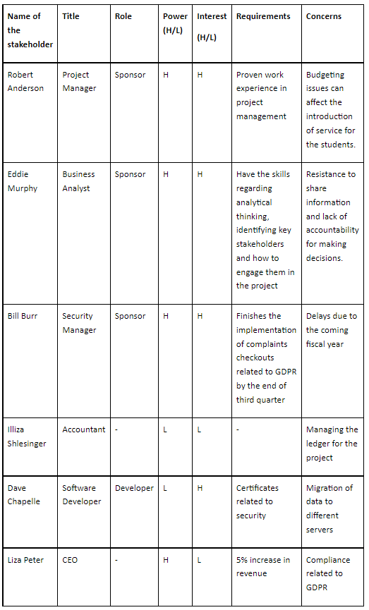
Table 1: Stakeholder List for the proposed case study
(Source: Created by the author)
b. Areas of Influence and Power/Interest Grid
In a project, the top management, team members, manager, peers, resource manager, and internal customers constitute the internal stakeholders while the external customers, government, contractors and subcontractors, and suppliers constitute the external stakeholders. The various types of stakeholder matrices are: Power interest matrix, Stakeholder analysis matrix, Stakeholder Engagement Assessment matrix. One can determine who has high or low power to affect the project, and who has high or low interest when plotting stakeholders on a power/ interest grid. It is required to keep people with high power satisfied and people with high interest informed. In stakeholder management, the simple tool that helps in categorizing project stakeholders by the power and influence they have on the project is called the Power/Influence Grid or the Power/Influence Matrix. And the technique used for categorizing stakeholders based on their power or influence and interest in a project is called the Power-Interest Grid. Stakeholders can be identified by looking at the existing documentation, organizing workshops, developing ‘as is’ business process maps and simply talking to people within the business. In this case study the name of the stakeholders is: Robert Anderson, Eddie Murphy, Bill Burr, Lliza Shlesinger, Dave Chapelle, and Liza Peter (Baernholdt et al. 2018).
c. Definitions of stakeholder’s power and interest
In any project, it is found that stakeholder management is an essential concept. Managing the stakeholders can help in successful completion of the project. In this study, the researcher focuses on the case of Student Gigz Pty Ltd. which now tries to launch a short-term assistance service for the student. Once, the stakeholders for this study have been identified, it is now important to prioritize them (Nguyen, Mohamed & Panuwatwanich, 2018). Prioritization of stakeholders becomes easy with the help of Power/Interest Grid.
From the above list formulated by the researcher for identification of the stakeholders, power and interest for different stakeholders have been highlighted. As observed from the table, the power and interest of the project manager, both are high. That means, engaging the project manager in this case would be beneficial in fulfilling the requirements. At the same time, power and influence for business analysts is also high. Managing both these stakeholders closely is quite essential. On the other hand, the CEO of this company shows high power but less interest (Campagne & Roche, 2018). That means, putting enough work in with such kind of people is required for achieving satisfaction. The software developer of this project shows low power but high interest. So, providing adequate information to such people and talking constantly with them can help in ensuring that there are no major issues. Moreover, the accountant is less powered and also less interested. Again, monitoring the accountant is important. Security manager for the same project shows high power and high interest. This shows that Engagement of the security manager will allow in securing the application and hence data breaching is not possible.
2. Elicitation Activity Plan
a. Four Elicitation Methods
An elicitation method is a collection of data that is used to gather information from people in fields related to education, knowledge engineering, management and so on. There are four elicitation methods which include interviews, user observation, use cases and prototyping.
b. Explanation of each method and selection
Interviews are used for collecting data from a small group of people on a specific topic. Generally, there are two types of interviews: they are structured and unstructured. In structure interviews the questions are placed with multiple choice answers for each subject and people are given choice to answer according to their view point (Pacheco, García & Reyes, 2018). But, in unstructured interviews questions depend on answers based on previous questions, a fixed set of answers is not possible here.
User Observation- It is based on observing a user or group of users regarding their behaviour with the product which they use in their daily life. This method can give qualitative output.
Use Case- This method is used for identifying system requirements and is used for organizing it. Moreover, this method is based on interaction between users related to a particular topic.
Prototyping- Prototype method is a method used for development in software like a prototype is built, tested and reworked. Rework is done until an acceptable prototype is attained.
For the case of Student Gigz Pty Ltd, the researcher takes the help of Use case. This is considered to be the foremost method for elicitation activity plan as it helps in explaining the system process and provides ideas accordingly. It includes four elements like Actor, Stakeholder, Primary Actor, Preconditions, Triggers, Main Success Scenarios and Alternative Paths.
c. Example of information gathering tool
The information gathering tool used for interviews is Questionnaires. In this the questions are placed with multiple choice answers for each subject and people are given choice to answer according to their view point.
On-site observation can be used as the information gathering tool for observing users’ activity. It is used in identifying people, objects and the information that is collected through this method is used for noting.
Use Case can be developed using Case studies. This method can be used in identifying and organizing system requirements which is based on interaction between users related to a particular topic (Rafiq et al. 2017).
Sketch can be referred to as the information gathering tool for prototyping. It is providing a prototype with designs and animations which is convenient for users to understand data. But, this method requires artboards in a document.
d. Stakeholders involved for elicitation activity
Project Manager is responsible for planning, procurement, and execution related to the project. Project Manager helps its team members by guiding them the right path. They show their leadership qualities by hiring employers fit for the job. In this case, the project manager is responsible for conducting interviews with business analysts to identify the key requirements for the proposed solution.
Business Analyst and security manager is responsible for conducting research and provides analysis for optimal business operations and services, they do their jobs in an efficient and productive manner. It also includes coordination with different departments to develop functional services, setting goals and budgets, managing schedules, and establishing new projects to improve organisation’s performance (Tiwari & Rathore, 2017). In this case, the business analysts and security manager are responsible for observing the behaviour of the user and then identify the best services that can be provided to them.
Software Developers will here try to design the use case for the system. Through this, it would be easier to see how different actors are associated with this system and helping to organize the requirements. Apart from that, the software developer will also try to design the prototypes for the system. With the help of a prototype, it would be easier to test the overall concept or process.
Conclusion
From the comprehensive study, it can be said that stakeholder management is vital as this is the lifeline for effective completion of the project. There must be efficient involvement of stakeholders for the fulfilment of the project. Meanwhile, requirements elicitation is also required for completing the project. The overall study has been conducted by considering the case of Student Gigz Pty Ltd. This company wishes to introduce an application for the student that will help them in getting short-term assistance. With the help of this study, the researcher tried to focus on identifying the stakeholders and prioritizing them on the basis of their job roles. For the sake of prioritization, the stakeholder took the help of Power/Interest Grid. Moreover, here different techniques of elicitation have been discussed and then applied for different involved stakeholders. Along with that, here, the researcher also mentioned different information gathering tools for the mentioned techniques.
References
Baernholdt, M., Dunton, N., Hughes, R. G., Stone, P. W., & White, K. M. (2018). Quality measures: A Stakeholder analysis. Journal of nursing care quality, 33(2), 149-156. Retrieved on 8th March 2021 from: https://journals.lww.com/jncqjournal/Fulltext/2018/04000/Quality_Measures__A_Stakeholder_Analysis.10.aspx
Campagne, C. S., & Roche, P. (2018). May the matrix be with you! Guidelines for the application of expert-based matrix approach for ecosystem services assessment and mapping. One Ecosystem, 3, e24134. Retrieved on 8th March 2021 from: https://hal.archives-ouvertes.fr/hal-01785010/
Nguyen, T. S., Mohamed, S., & Panuwatwanich, K. (2018). Stakeholder Management in Complex Project: Review of Contemporary Literature. Journal of Engineering, Project & Production Management, 8(2). Retrieved on 8th March 2021 from: https://www.researchgate.net/profile/Tuan_Son_Nguyen/publication/326801226_Stakeholder_Management_
in_Complex_Project_Review_of_Contemporary_Literature/links/5b63e5f80f7e9b00b2a25354/Stakeholder-
Management-in-Complex-Project-Review-of-Contemporary-Literature.pdf
Pacheco, C., García, I., & Reyes, M. (2018). Requirements elicitation techniques: a systematic literature review based on the maturity of the techniques. IET Software, 12(4), 365-378. Retrieved on 8th March 2021 from: https://digital-library.theiet.org/content/journals/10.1049/iet-sen.2017.0144
Rafiq, U., Bajwa, S. S., Wang, X., & Lunesu, I. (2017, August). Requirements elicitation techniques applied in software startups. In 2017 43rd Euromicro Conference on Software Engineering and Advanced Applications (SEAA) (pp. 141-144). IEEE. Retrieved on 8th March 2021 from: https://ieeexplore.ieee.org/abstract/document/8051340/
Tiwari, S., & Rathore, S. S. (2017). A methodology for the selection of requirement elicitation techniques. arXiv preprint arXiv:1709.08481. Retrieved on 8th March 2021 from: https://ieeexplore.ieee.org/abstract/document/8051340/
Case Study
MEM602 Engineering Risk Management Assignment Sample
Assignment Brief
Individual/Group - Individual
Length - 2000 words +/- 10%
Learning Outcomes
The Subject Learning Outcomes demonstrated by successful completion of the task below include:
a) developing a systematic risk management approach to strategically and operationally identify, evaluate, analyses, manage and govern risks in an engineering context
b) implementing a risk management approach in engineering practice workplace situations
c) assessing and applying methodologies and tools to improve safety, reliability and to reduce hazards.
Submission - Due by 11:55pm AEST/AEDT Sunday end of Module 3.
Weighting - 30%
Total Marks - 100 marks
Task Summary – Assessment 1
For Assessment 1, you are required to develop a risk strategy. You will be required to provide a formal report in 2000 words (+/- 10%) that outlines a risk strategy for the attached Case Study. Please note, this is an individual assessment, and it is expected that you undertake appropriate academic cues in preparing your submission.
Context – Assessment 1
The Case Study provides an overview of a specialist manufacturing organization operating in NSW, Australia. A number of attributes have been provided in the Case Study to give the reviewer (i.e., you as student) the opportunity to draw on material and construct a response that is relevant to the information provided (in the Case Study). Reference to the Case Study is required for ALL three assessments, and your critique of the Case Study will differ across ALL three assessments.
For Assessment 1, you are required to develop a risk strategy for the Case Study. The Managing Director has assigned the Project Engineer (you) to develop a risk strategy for the organization. It has become apparent to senior management that whilst key personnel across the organization have independently managed their work units and processes and the risks associated with these, an in- depth review at a strategic level has yet to take place. As Project Engineer, you will be required to provide a formal report that outlines a risk strategy for the company. Your report will be broken into 4 main categories: people, reputation, business process and systems and financial. Within these categories, you will address the scope of risk: development and evaluation of good governance principles, identification of any external and internal risk-related issues (including systemic risks) and stakeholder responsibility together with risk reporting across the company and any affiliated entities. Collectively, these factors will be discussed in the four main categories to outline the role of compliance leading to the development of a compliance policy for the company and any affiliated entities. It is expected that your report will focus on these aspects and not just on reporting a risk management plan. However, risk management tools and guides such as the Hierarchy of Controls and reference to industry standards (and others if deemed necessary) can be used to support your argument.
Report structure for assignment help
1. Executive Summary (what is the purpose and nature of the report)
2. Contents page
3. Introduction — Background information
4. Body (as outlined in report criteria)
5. Conclusion
6. Recommendations
7. List of References
8. Appendices
Referencing
It is essential that you use appropriate APA style for citing and referencing research. Please see more information on referencing here: https://library.torrens.edu.au/academicskills/apa/tool
Submission Instructions
Submit this task via the Assessment link in the main navigation menu in MEM602 Engineering Risk Management. The Learning Facilitator will provide feedback via the Grade Centre in the LMS portal. Feedback can be viewed in My Grades.
Case Study
Description of organization:
MDF Manufacturing is a small to medium-size enterprise located in the Central West and Orana District of NSW, Australia. MDF provides melamine particle-board manufacturing finishing services to wholesale, specialist retail suppliers and small businesses, both intrastate and interstate. State-of-the-art machinery and manufacturing finishing techniques allow MDF to supply and compete in very competitive kitchen and decorative door, panel and laminate markets. An engineering logistics/services workshop is operated from the site. The site is situated adjacent to a major road route in a rural area governed by the Central West and Orana Municipal Council. The MDF workforce comprises 155 employees, all of whom travel to the organization for work from within the local area in their own vehicles.
Senior Management at the MDF site:
• Managing Director (Sales and Marketing)
• Regional Sales Manager
• Project Engineer
• Logistics/Purchasing Manager
Other key personnel:
• Safety Officer
• Site Supervisor
• Maintenance Supervisor
• Warehouse Day Shift Supervisor
• Accounts Manager
• Site Operators
• Maintenance Operator
• Warehouse Operators
The facility is open 6 days a week / 24 hours a day and has no recognized holiday or shut-down periods, except for wo days at Christmas and two days over the Easter vacation periods.
Site setting:
Founded in 1985, the site comprises a shared maintenance garage, engineering logistics/services workshop, open-air vehicle parking, manufacturing/finishing complex and a single-storey office block situated on a formerly green-field site. To the North, there is arable farmland with 25-metre poplar trees along the boundary fence. On the Eastern boundary, there is a separate organization specializing in haulage and logistics. To the South, there is a service road, which acts as the main access road for vehicles to and from the site to the major road route and local country lanes. The Western boundary is separated by a small stream, used by anglers throughout the season. The site has a 3- metre-high mesh fence around the perimeter and a barrier at the main entrance.
Utilities:
Heating for the garage, manufacturing complex and offices is provided by natural gas. Part of the Manufacturing complex has comprehensive vented ducting with controlled airflow systems driven by electrical power.
Water: 16,000 m3 per year received from municipal supply. It is used in manufacturing processes, shared maintenance garage, wash-off, cleaning, heating, and so on.
Electricity: 1,800,000 Kwh per year.
Wastes: Solid waste from the manufacturing operation is collected from the workshop and shared garage operations, and placed in skips for transfer to the local waste disposal site. Of all the manufacturing maintenance waste – oil, filters, worn components, processing waste from manufacturing equipment and fume extraction (low Formaldehyde emitting) – some is segregated, recycled, and extracted by approved sub-contractors. Solid wastes are stored in skips on compacted ground bordered by unsurfaced soil. Liquid wastes are stored in 205-litre drums in the same area.
Fuel:
Diesel fuel is delivered to the site on contract and stored in two 30,000-litre elevated tanks located against the western boundary and surrounded with bunding (secondary containment) of a 110% capacity. This arrangement is shared with the Haulage and Logistics Operation.
Activities:
1. Primary finishing: trimming, sanding and upgrading of the plywood after pressing, is undertaken so as to enhance the marketability of the product.
2. Trimming saws cut the plywood boards to the required size, which are then sanded in machines fitted with wide-belt or drum sanders so as to obtain the desired surface smoothness.
3. Plywood is then produced in a wide range of sizes and thicknesses.
4. The product is sorted, packaged and allocated into lots ready for transport.
Solution
1. Introduction
The report focuses on the risk strategy of MDF, a small-scale manufacturing organization that supplies melamine products to retailers, wholesalers and suppliers across various states. This report discusses a risk strategy concerning people, organizational reputation, business process, and finances. During the Covid-19 pandemic Australian government as well as SMEs increase their expenditure in order safeguard the life of people that seems utmost crucial to increase the organizational reputation (Referred to the Appendix 1). The scope of risk is identified by developing and evaluating a good governance principle. The risk-related issues concerning the internal and external environment will be discussed in the report. The compliance policy and risk assessment through stakeholder responsibility will be provided in this report.
2. Risk Strategy
Risks privileged in several aspects
People-Working in the manufacturing sector has some hazards associated with it. The natural gas supply provides the heating of the garage, and the leakage may have some hazardous effect on the environment. Exposure to natural gas can have a life-threatening impact on employees. In this regard, it is found that mainly four types of natural gases are existing in Australia which are shale gas, tight gas, coal seam gas and conventional gas (Referred to the Appendix 2).
Reputation- Solid waste management is an important part of business as environmental pollution is an alarming problem. The organization performs its solid waste management process as many materials from the garage, and the workshop is collected. Approved contractors recycle the waste like oil, filters, the processing. If any negligence takes place in this regard, the reputation of the organization will suffer. Public-private partnership organizations suffer from risks like inflation, corruption, delay in completion, exchange and interest rate fluctuation. They release their waste to the disposal site locally, failing which may degrade their market value. They offer melamine particle board to suppliers, retailers both in a small and medium-sized business. The quality needs to be maintained. Otherwise, they may lose their business.
Business processes and system- The business process risks may include labor cost, transportation and logistics, inventory management, supply chain and regulatory or trade policies. Purchasing organizations are exposed to risk in their interaction with the suppliers (Osei-Kyei&Chan,2017). The task associated with the site is fuel storage and refueling, surface water discharge, water storage and disposal and compression planning. All these issues need to be properly handled; otherwise, storage pipe leakages can cause serious damage to the organization.
Financial risk-The budget of the raw materials and the cost of labor are some of the issues that may lead to serious issues later. The raw materials are natural gas for heating the garage and other materials used for preparing melamine products if the budget exceeds due to wastage and low quality of the materials, which is a potential risk for the organization.
3. Scope of Risk
3.1. Development and Evaluation of governance principle
The governance principles for a risk management plan are:
• Identify and assess the factors that are related to the risk.
• Evaluate the likelihood for risk to occur
• Develop strategies to mitigate the risk factors.
• Prepare a risk management plan.
• Evaluate the strategies of risk management.
The security governance policies must have some rules and regulatory principles that offer compliance to the industry and the organizational laws. International Risk Governance Council includes the economic, social, cultural perspectives of risk and develops plan through communication with stakeholders and involvement (der Vegt,2018). It is necessary to inform all the internal and external stakeholders regarding the policies, and everyone should abide by the industry standards related to risk strategy.
Evaluating the principles
A good governance principle must be participatory, efficient, responsive, effective, consensus-oriented, equitable, responsible and inclusive. For evaluating the process, proper testing of the principles needs to be performed, which is achieved by collecting information from the stakeholders of the organization. Interview, survey methods, and questionnaires are ways of collecting feedback from the employees and other shareholders. Their opinion will help assess the risk management plan's effectiveness, and any necessary alterations can be implemented. Past experiences and information from the market can help make good governance policies that reduce the probability of any hazards or risk associated with a business process. Enterprise Risk Management Plan is gaining popularity and induced by regulatory requirements (Sax &Andersen,2019). The risk can be operational where there is some flaw in the working process of the organization or failure of management or financial crisis. A proper evaluation and development of governance principles will help in identifying and mitigating the risks. For NDF, governance policy must define the ways of dealing with solid waste and the use of natural gas without any accident.
3.2. Identification of the internal and external risk-related issue
In the business of MDF, there are several internal and external risk-related issues. Firstly, the company may face issues to maintain business operations properly due to the shortage of employees. It is observed that there are only 155 employees in MDF to manage business operations. However, the company is associated with various activities such as trimming plywood, upgrading it, sanding and others. Therefore, it is a significant risk in the business of the company.
Along with this, wastes from the business is another internal business risk of MDF. For this purpose, the company needs to adopt a specific policy for waste management to maintain solid waste, worn components, oil, filters and so on. This waste can impact the environment of the industry negatively and may reduce the competitive advantage of MDF.
On the contrary, some external risk is associated with the businesses of MDF also. It is noticed that there are several particleboard manufacturing companies in Australia, such as D&R Henderson, Famitchell and others. That is why the existence of many leading particleboard manufacturing companies is a significant risk. MDF has to develop its business strategy accordingly to sustain its profitability among other competitors.
3.3. Stakeholder responsibility in the risk reporting across MDF and affiliated entities
As Hein et al. (2017) mentioned, stakeholder refers to the people interested in business activities and operations. Business risk affects the stakeholder interest of companies. That is why the stakeholder is responsible for the risk reporting and needs to help in the strategy for overcoming the risk. The major stakeholders of MDF are the key employees, suppliers, warehouse operators and others. Therefore, the CEO of MDF needs to report to the stakeholders about the potential risk of business in risk reporting.
The affiliated entity in the organization is the direct or indirect control of another entity. The other entity could be the subsidiary company or parent company. However, considering the business risk of MDF, it can be stated that the company would be beneficial with the entry of the subsidiary company. Through this, it would be possible to maintain the company's business activities properly with the help of the other organization. As subsidiary companies are other major stakeholders of the organization, the risk report of MDF is presented to the stakeholders to mitigate the company's risk significantly.
4. Role of the compliance for MDF and affiliated entities
Compliance in business refers to the relevant laws and regulations which organizations have to follow. In the view of Fiandrino, Busso&Vrontis (2019) compliance identifies the risk of the organization and assesses them properly. As there are many risks associated with the business of MDF; therefore, compliance plays a vital role in the business of MDF. The rules and regulations of MDF need to be implemented properly to avoid such risk. In Australia, there is a fair work act of 2009, which has to be followed to maintain the minimum standard of employment and entitlement in the country. Through following this, it is possible to retain the employees and improve the effectiveness of the company. As it is mentioned that there are many business activities in the business of MDF. Therefore, retaining the employee base will be effective to manage all the operations properly. Another major importance of compliance in business is, it helps to monitor the effectiveness of the risk management and help in the risk exposure. It is noticed that MDF has different employers for managing different business activities such as safety officer, site operator, accounts manager and others. Therefore, considering this, it can be stated that MDF has the proper resources to manage the potential risk and to develop the manufacturing operation.
Entity compliance defines the process and practices of business with regulatory and financial compliance. It is mentioned that through a subsidiary entity of another company in the business of MDF, the company can achieve maximum outcome business. In this case, compliance will help associate the other company in the business of MDF in a proper legal manner. Hence, compliance has an effective role in the business of MDF and the affiliated entity.
5. Compliance policy of the company and affiliated entities
As Haugh (2017) stated, corporate compliance refers to the internal policy and procedures for preventing the employees from violations of ethical standards, regulations, and others. In this way, compliance policy is involved with the risk management and internal monitoring and control of the organization legally. Considering this, it can be mentioned that the MDF needs to follow the Corporations Act of 2001 for managing their business in the market of Australia. Following the proper compliance policy will help manage the people, activities, finance and other aspects of the organization. A proper compliance policy enables the MDF to monitor and control the internal business process of the company. It effectively reduces the legal issues of the organizations and will enhance the public relation of MDF with their employees and other stakeholders. Along with this, as it is observed that the shortage of employees is a major issue of the organization; therefore, compliance policy will foster the employees' trust towards the organization and be effective in retaining the employee base for managing the organizational activities.
The compliance policy of MDF needs to be applied in the affiliated entity of the organization as well. By applying proper compliance policy, the association of the MDF with other organizations could be generated legally. As MDF is a small to medium-sized particleboard manufacturing company in Australia, an affiliated entity in the organization will enable the company to achieve a huge customer base and be effective in developing the market. Along with this, compliance policy will improve the organizational and operational efficiency of MDF and, in this way, will provide a significant competitive advantage for the organization. That is why, to manage the risk in the business of MDF, adopting a proper compliance policy is important.
6. Conclusion
From the report, it can be concluded that a risk mitigation plan is essential for an organization. Good governance policies are necessary for evaluating a risk management plan. The stakeholder responsibility is associated with proper governance of the plan, and the duties and responsibilities need to be clearly stated. A compliance plan that supports industry standards helps manage the risk associated with the business. A recommendation plan is developed for the risk strategy that will help NDF gain insight into the internal and external issues and eliminate the factors that are re-associated with a risk management plan.
7. Recommendations
• It is necessary to remain open to any changes that are required in future as the future is unpredictable, and any unprecedented risk may surface in future.
• The organisational culture is an important aspect where the stakeholders must learn from their mistakes and ready to change whenever necessary.
• The duties and responsibilities of each stakeholder must be properly stated. The governance principles must provide a clear description of the risk management policies and techniques associated with the potential factors of risk.
• A proper strategy is essential for risk assessment, and professionals need to be introduced to make an effective policy.
• The internal control, policy governance and quality control, and security issues need to be properly handled by the organisation's key personnel.
• MDF uses the open area for vehicles, and they offer natural gas as a source of energy. Instead of that, using renewable energy resources will help in dealing with environmental issues.
• Solid waste needs to be recycled, and the disposal process must follow e-waste management procedures governed by state laws.
• Cost overrun is a major reason for project failure. Some factors like low advance payment, use of innovative technology, unclear specifications are some of the reasons that are related to chaos (Afzal et al. 2019). It is necessary to keep the project under the propped budget through proper policies and governance.
References
Afzal, F., Yunfei, S., Sajid, M., & Afzal, F. (2019). Integrated priority decision index for risk assessment in chaos: cost overruns in transport projects. Engineering, Construction and Architectural Management, 27(4), 825–849. https://doi.org/10.1108/ECAM-02-2019-0079
Der Vegt, R. G. (2018). Risk assessment and risk governance of liquefied natural gas development in Gladstone, Australia. Risk Analysis, 38(9), 1830–1846. https://doi.org/10.1111/risa.12977
Fiandrino, S., Busso, D., &Vrontis, D. (2019). Sustainable responsible conduct beyond the boundaries of compliance. British Food Journal, 121(5), 1035–1049. https://doi.org/10.1108/BFJ-03-2019-0182
Haugh, T. (2017). Nudging corporate compliance. American Business Law Journal, 54(4), 683–741. https://doi.org/10.1111/ablj.12109
Hein, A. M., Jankovic, M., Feng, W., Farel, R., Yune, J. H., &Yannou, B. (2017). Stakeholder power in industrial symbioses: a stakeholder value network approach. Journal of Cleaner Production, 148, 923–933. https://doi.org/10.1016/j.jclepro.2017.01.136
Osei-Kyei, R., & Chan, A. P. C. (2017). Risk assessment in public-private partnership infrastructure projects. Construction Innovation, 17(2), 204–223. https://doi.org/10.1108/CI-08-2016-0043
Sax, J., & Andersen, T. J. (2019). Making risk management strategic: integrating enterprise risk management with strategic planning. European Management Review, 16(3), 719–740. https://doi.org/10.1111/emre.12185
Research
MEM603 Engineering Strategy Assessment Sample
Question:
In this assessment, you are required to research, assess and compare the engineering strategies of two major automotive companies. The engineering strategies need to be current and future-oriented. You will be provided with a list of major automotive companies from which you can choose two companies. You should prepare for and approach this task by reviewing the content and readings provided in Module 1 (Strategic Business Planning), Module 2 (Innovation Strategy and Management) and Module 3 (Technology and R&D Strategy and Management) and conducting research of publicly available information. Please note that the focus of the assessment should be on the improvement of engineering operations via R&D, innovation and technology (including intellectual property).
It is suggested that you use the following as a guide to structure your assessment: 1. Introduction • Summarise the background information provided; and • Outline the backgrounds of the two global automotive companies. 2. Literature Review • Conduct a literature review of each selected automotive company and summarise the research. 3. Analysis and Findings • Discuss and compare the strategies of the selected automotive companies based on the information you gathered in your literature review. 4. Conclusions 5. References 6. Appendices
Answer:
Introduction
Summarisation of background information
The automotive industry uses modern technological development and innovation to create an established organisational structure to drive growth in its business (Slansky, 2022). Automotive organisation and their lines of products are using artificial intelligence implementation in multiple manners. Artificial intelligence will include the modern production of human-machine interaction, intelligent robots, and a substantial assurance quality process. Artificial intelligence is used fundamentally in designing cars, and manufacturers use machine learning and artificial intelligence to create their manufacturing processes. In lines of production assembly, robotics is implemented to develop that are used several times.
Background of the companies
The Jaguar Land Rover is a renowned automobile company fostering unique technological development and innovation. The computing stability of the Jaguar land rover is more excellent and more sustainable than Space Shuttle. It can handle twenty-one thousand messages alternatively and at a regular speed of about 100 MB networks of ethernet (Jaguarlandrover, 2022a). The automobile is always remained connected with Wi-Fi, 4G, and cloud computing. The car manufacturers had implemented software over the air technology to regulate updates to get delivered according to services and functions. BMW is another well-known manufacturing company regulating sustainable technologies to control high voltage batteries that are installed in the car company. Another technology implemented at Din golfing is a smartwatch that is changing along with the containers. The augmented reality glasses increased their production by twenty-seven per cent, which reduced their error rate by 34% during packing and scanning (Jones, 2022).
Literature Review
Innovation
BMW is the leading selling car manufacturing company and has always regarded creativity as an essential element to conduct success in the BMW group (Steelcase, 2022). A tidal regulated change moves between the industry to create rapid innovation within the car company. For example, they innovate autonomous driving, which is expected to develop their business model within the last thirty years. To be a leading car company, BMW has realised the vitalness of developing their innovation process to create a systematic approach.The management also recruits talented car designers that would create sustainable automobile technological development. It can be argued that, diversification can be very helpful in managing and executing innovation within the workplace. According to Markides (1997), diversification is one of the high-stake games as companies need to make a decision regarding thoughtful deliberation.
Along with the advancement of time, BMW's business model is changing along with the automated driving that is reshaping their success in the market. Digital technology has been fundamentally ubiquitous and developed, technological devices have become more interdependent and creative, teamwork and collaboration are developing as a vital aspect. The company has adopted digital location and mapping known as HERE (HERE, 2022). However, the deal was between Jaguar Land Rover and Daimler in 2015. HERE regulated services that are required by both locations and autonomous driving services. Modern technology HERE provided eminent services required for both location-driven services and autonomous driving. The windscreen wipers are integrated into the system and are shared within the management system of the company. Innovation was transforming the production process of BMW to regulate the process of production (Frangoul, 2022). The company uses robots and technology to guide employees and people working in manufacturing companies to sort out heavy lifting and transport elements. Jaguar Land Rover has worked with labs of innovation with sustainable stem to enhance organisations to develop technological developments and vehicle production. The innovation program's common goal aligns with participating industrial products and technologies into the automobile ecosystem. The engineering segment of Jaguar Land Rover has a direct association with the decision-making process. The straight path towards integrating substantial vehicles demonstrates the automated functional concept in the company. Jaguar Land Rover company is formulating digital transformation with international-based brands after their Accenture appointment. Accenture would associate forces with Land Rover's brand-named Spark 44 as an essential client automated venture to develop a modern automated model (Accenture, 2022). The venture will regulate a vital role in developing JLR to shift towards the modern, electric-based business. The company will attain advantages from various models of ownership that are designed to be fit within the individual manner of living. Accenture was selected as the sustainable technological, data generated, and experience generated approach.
Technological Advancement
During 2021 BMW Group has planned ambitious development for profitability and growth that developed immense forerunners for evaluating developed technological offensive in upcoming times. In 2014, the BMW company developed a booking option that can be done through digital services directly from automobiles through the connected drive of BMW store (BMWgroup, 2014). However, during 2018 the manufacturers maintained their vehicles up to date along with modern technological software called software up-gradation, similar to updating the modern software for mobile devices (Automotive World, 2022). The company has chosen significant powertrain from electric power to combustion engines in the second transformation phase. The subsidiaries are the moderate architecture of vehicles that enable an interchangeability network between multiple drivetrains combined closely.The eighth operating system launched in 2021 is a strong in-vehicle that processes important data within its operating system (Automotive World, 2022). The BMW I-drive is the safest and simplest concept of the operating system installed in the vehicle. The vehicles create remote up-gradation to develop sustainable installation and up-gradation.The production lab of Jaguar Land Rover is currently analysing the headset advancement of technology for creating digital applications. The designing engineers and planners can integrate the validation of products in creating process planning and factory restoration. Jaguar Land Rover also proposes technological training techniques that work with the complex technology of batteries. The solution of modular allowed the practical usage of virtual reality and augmented reality training.In the view of Li et al. (2021), virtual reality is a common substantial application to measure the implementation of virtual reality applications.However, the technological simulation adopts complex challenges that are flexible and easy to adapt to. The simulation fundamentally has made the path for an easy decision, guides to ignore waste, and thus contributes towards implementing emerging resources. Jaguar Land Rover announced that the assembly of modular aspects would have a productive increase of about twenty per cent compared with lines of production.
Analysis and Findings
Comparison between two companies’ strategies
• BMW Group has used artificial intelligence as an essential technology is a substantial element to regulate digital development. The organisation has implemented artificial intelligence throughout various aspects of the value chain, generating it as the fundamental value for processes, consumers, employees, and products. In addition, the BMW company has essential competence for encouraging data analytics and machine learning. On the other hand, Jaguar Land Rover's clear sight technologyhas regulated modern automobile generations more advanced and sustainable automobile equipment. The technology includes 5 cameras and fourteen ultrasonic sensors to generate an interactive three-hundred-and-sixty-degree view around the automobile vehicle. The clear sight allows the drivers to shift between high-definition mirrors to interior mirrors to show a good view behind the car.
• According to Kukkamalla, Bikfalvi, &Arbussa (2020), BMW Group is a well-known and leading automobile firm not regulating premium pricing on their products but also generating a good relationship with the consumer with on-demand, telematic and financial services. In 1997 the company had launched digital services. The company also has enhanced its organisational culture to increase its growth and development. On the other hand, JLR has regulated secure blockchain technologies to create proper supply chain management to generate complete transparency within a generated supply chain management. The digital technique enabled by JLR to examine the carbon footprint for its leather supply chain management.
• Qualcomm Technologies has announced its association with BMW Group, and together they will bring collaboration in the latest automobile technologies and automated driving medium. Qualcomm is a wireless technological organisation driving technological advancement by bringing 5G expansion. On the other hand, JLR has developed the application of augmented reality to create designing modern technological applications. An idle motion tracking equipment is implemented to develop the orientation and position of the reviewer's feedback around significant prototype (Mechdyne, 2022).
Innovation
• Jaguar Land Rover aims to create a sustainable business without minimising carbon emissions. The company focuses on creating zero waste that enables them to develop their zero regulation of manufacturing process. Innovation is an essential medium to create unique products in the automotive industry. For achieving innovation an organisation needs to create an appropriate integration with its R&D process and marketing channels (Cotterman et al., 2009). The company will fundamentally undergo a renaissance to evolve as the unique electric automobile industry with a substantially beautiful modern portfolio to engage modern generation and designing technologies (Jaguarlandrover, 2022b).
• The company has always focused on consumer preferences and choices regarding the specific product. The centralised medium for the company will focus on their engineering, materiality, and manufacturing financial investments. On the other hand, BMW considers itself as the automobile industry player developing modern services and substantial innovator for a successful model for business.
Conclusion
As per the above discussion, it can be concluded that both the companies focus on innovating their product line in order to capture a considerable market share. Also, it can be asserted that both the companies are dominating their markets by providing high-quality and luxurious products to their customer base. Although it can be recommended that both organisations need focus precisely on developing EVs as in the upcoming few years, the market will be captured by EVs. Moreover, BMW always has maintained its consumer-centric approach to calculate dynamic market approach and conditions in the market to develop their marketing innovation. The company also receives a substantial revenue amount from necessary services. The company also depends upon integration, technology, dynamic abilities, and collaborations to create professional activities. The BMW has enhanced the service integration method by creating collaborative programs with multiple stakeholders such as providers in communication and technological companies. Both the companies will enhance their effective standing communication to generate smart, safe, and sensitive driving experiences at BMW companies.
References
Accenture. (2022). Jaguar Land Rover transforms global marketing communications model.https://newsroom.accenture.com/news/jaguar-land-rover-transforms-global-marketing-communications-model.htm#:~:text=Accenture%20will%20join%20forces%20with,%2Dfirst%2C%20modern%20luxury%20business.
Automotive World. (2022). A New Era, a New Class: BMW Group steps up technology offensive with comprehensive realignment – uncompromisingly electric, digital, and circular | Automotive World. https://www.automotiveworld.com/news-releases/a-new-era-a-new-class-bmw-group-steps-up-technology-offensive-with-comprehensive-realignment-uncompromisingly-electric-digital-and-circular/.
BMWgroup. (2014). Sustainable value report. https://www.bmwgroup.com/content/dam/grpw/websites/bmwgroup_com/responsibility/downloads/en/2014/BMW_Group_SVR2014_EN.pdf.
Cotterman, R., Fusfeld, A., Henderson, P., Leder, J., Loweth, C., & Metoyer, A. (2009). Aligning marketing and technology to drive innovation. Research Technology Management, 52(5), 14–20.https://lesa.on.worldcat.org/oclc/7025678976
Frangoul, A. (2022).How technology is helping transform BMW’s business.https://www.cnbc.com/2018/01/18/how-technology-is-helping-transform-bmws-business-model.html.
HERE. (2022). BMW Real Time Traffic & Navigation Partnership | HERE. https://www.here.com/strategic-partners/bmw.
Jaguarlandrover. (2022a). Innovation | JLR Corporate Website. https://www.jaguarlandrover.com/innovation.
Jaguarlandrover. (2022b). Jaguar Land Rover Reimagines The Future Of Modern Luxury By Design | JLR Media Newsroom. https://media.jaguarlandrover.com/news/2021/02/jaguar-land-rover-reimagines-future-modern-luxury-design.
Jones, V. (2022). Innovation and smart tech: Why BMW is driving both. Automotive Logistics. https://www.automotivelogistics.media/innovation-and-smart-tech-why-bmw-is-driving-both/22219.article.
Kukkamalla, P. K., Bikfalvi, A., &Arbussa, A. (2020). The new BMW: business model innovation transforms an automotive leader. Journal of Business Strategy.
Li, J., George, C., Ngao, A., Holländer, K., Mayer, S., &Butz, A. (2021). Rear-Seat Productivity in Virtual Reality: Investigating VR Interaction in the Confined Space of a Car. Multimodal Technologies and Interaction, 5(4), 15.
Markides, C. C. (1997). To diversify or not to diversify. Harvard Business Review, 75(6), 93–99. https://lesa.on.worldcat.org/oclc/5232897547
Mechdyne. (2022). JLR Selects Mechdyne for Innovative Augmented Reality Software and AV Technology for Design. https://www.mechdyne.com/jlr-selects-mechdyne-for-innovative-augmented-reality-software-and-av-technology-for-design/.
Slansky, D. (2022). Before you continue to YouTube. Youtube.com. https://www.youtube.com/business-intelligence/article/21579012/manufacturing-trends-and-technologies-in-the-automotive-industry.
Steelcase. (2022). How BMW Is Driving Innovation - Steelcase. https://www.steelcase.com/asia-en/research/articles/topics/innovation/bmw-driving-innovation/.

- Assignment - Child Care
- Assignment - Mathematics
- Assignment - Accounting
- Assignment - Auditing
- Assignment - Biology
- Assignment - Law
- Assignment - Management
- Assignment - Nursing
- Assignment - Finance
- Assignment - Computer Science and IT
- Assignment - Humanities
- Assignment - Economics
- Assignment - Statistics
- Assignment - Architecture
- Assignment - Engineering
- Assignment - cookery
- Assignment - Marketing
- Case Study - Chemistry
- Case Study - Accounting
- Case Study - Law
- Case Study - Management
- Case Study - Nursing
- Case Study - Finance
- Case Study - Computer Science and IT
- Case Study - Engineering
- Case Study - Economics
- Case Study - Biology
- Case Study - Auditing
- Case Study - Marketing
- Case Study - Project Management
- Coursework - Diploma
- Coursework - Accounting
- Coursework - Auditing
- Coursework - Biology
- Coursework - Management
- Coursework - Nursing
- Coursework - Finance
- Coursework - Computer Science and IT
- Coursework - Engineering
- Coursework - Humanities
- Coursework - Child Care
- Coursework - Project Management
- Coursework - Economics
- Coursework - Cookery
- Coursework - Law
- Dissertation - Accounting
- Dissertation - Auditing
- Dissertation - Biology
- Dissertation - Law
- Dissertation - Management
- Dissertation - Nursing
- Dissertation - Finance
- Dissertation - Computer Science and IT
- Dissertation - Humanities
- Dissertation - Economics
- Essay - Politics
- Essay - Childcare
- Essay - Accounting
- Essay - Biology
- Essay - Law
- Essay - Management
- Essay - Nursing
- Essay - Computer Science and IT
- Essay - Humanities
- Essay - Economics
- Essay - Auditing
- Essay - Engineering
- Essay - Architecture
- Essay - Finance
- Essay - Science
- Essay - Marketing
- Programming - Computer Science and IT
- Reports - Management
- Reports - Computer Science and IT
- Reports - Project Management
- Reports - Marketing
- Reports - Nursing
- Reports - Engineering
- Reports - Accounting
- Reports - Humanities
- Reports - Finance
- Reports - Architecture
- Reports - Biology
- Reports - Economics
- Reports - Childcare
- Reports - Law
- Research - Accounting
- Research - Auditing
- Research - Biology
- Research - Law
- Research - Management
- Research - Nursing
- Research - Finance
- Research - Computer Science and IT
- Research - Science
- Research - Engineering
- Research - Humanities
- Research - Economics
- Research - Project Management
- Research - Statistics
- Research - Architecture
- Research - Marketing
- Thesis Writing - Computer Science and IT
- Thesis Writing - Engineering
- Thesis Writing - Biology
- Thesis Writing - Finance
- Thesis Writing - Humanities
- Thesis Writing - Auditing
- Thesis Writing - Economics
- Thesis Writing - Law
- Thesis Writing - Nursing
- Thesis Writing - Accounting
- Thesis Writing - Architecture


.png)
~5.png)
.png)
~1.png)


.png)